The design and configuration of an electrical slip ring must consider the operation of the various types of the device and take into account several fundamental […]

The design and configuration of an electrical slip ring must consider the operation of the various types of the device and take into account several fundamental issues.
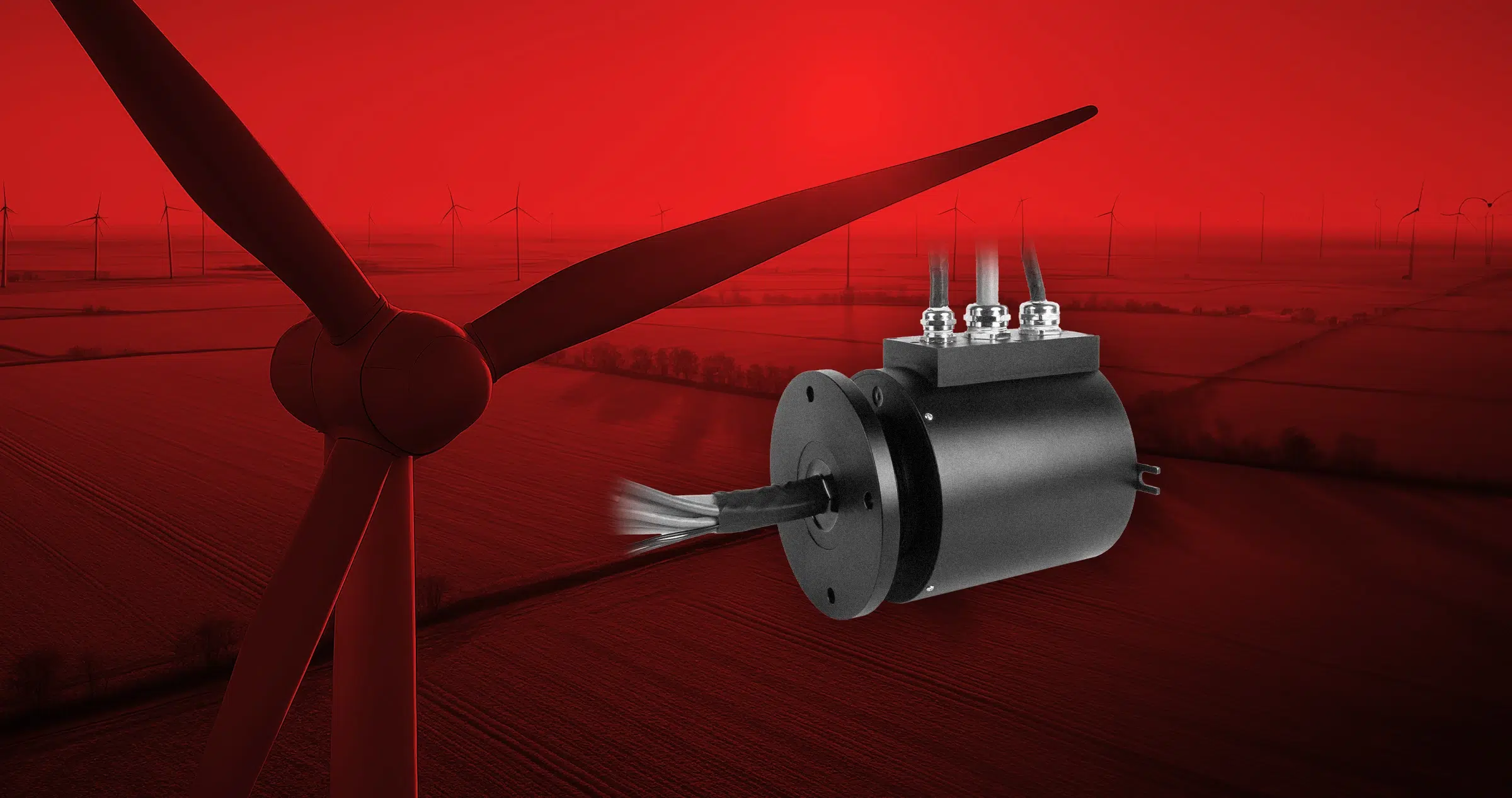
A slip ring is an electromechanical device that transmits electrical power and signals from a fixed part (stator) to a continuously rotating part (rotor), and vice versa.
It is clear that eliminating cable torsion greatly simplifies the design of machines and systems, as it avoids the need for complex cable runs. The machine also has no need to return to its initial position at the end of each cycle, thus improving both the performance and footprint of the application.
Power transmission ranges from a few mW to several MW, depending on the machine and its configuration. Data can also be exchanged via digital and analog I/O, as well as over the fieldbus at speeds of up to 1Gb/s.
Contact technologies
Given the vast range of uses of slip rings, a variety of contact technologies have been developed, employing diverse configurations and materials. Two main technologies are currently available: contact and contactless (wireless).
Contact slip rings utilize conductive brushes of various types, including monofilament, multifilament, graphite, and liquid metal. Contactless slip rings, on the other hand, may employ optical, inductive, or capacitive technologies.
In detail, the benefits of graphite brushes include current transmission from 50A to 400A, simple construction, and low production costs, even for high current-rated devices. However, they have disadvantages, which include the need for larger signal circuits, unsuitability for fieldbus signals with high data rates, the generation of dust while in operation, and the requirement for regular maintenance.
Metal brush slip rings, on the other hand, are typically more compact, offer high transmission rates, require minimal maintenance, and provide outstanding value for money, particularly for small units. Their disadvantages include limited current ratings (150-200A) and the high cost of solutions rated for more than 100A.
Turning to fiber brushes, these can be divided into monofilament and multifilament brushes. The former are smaller and lower cost. However, they have a limited service life (10 million revolutions), operate at a low rotational speed (up to 500 rpm), and offer only two contact points. Multifilament brushes, on the other hand, offer higher rotational speeds (up to 3000 rpm), more points of contact (and hence more stable transmission), last longer (up to 100 million revolutions), and are more robust—but they cost more.
Which slip ring should I choose?
To assure optimal operation in a given application, one must consider the following parameters:
- The fieldbus used to transmit data (Profibus, Ethernet, CANbus, etc.)
- The type of cable used to connect the slip ring, and the length of the cable run
- The data-rate/maximum frequency
- The signal-to-error rate
- Size (diameter/length)
- The number of circuits and their voltage and current ratings
- The maximum rotational speed of the application
- The ambient conditions
Even the simplest slip rings, with brushes and rings, can transmit power; however, choosing the right type of brush is critical.
The following parameters determine which type of brush is best for the application: current, voltage, rotational speed, and ambient conditions.
In power transmission, one must also consider the voltage drop across the slip ring and the effective current flow, because any losses affect the voltage available to the load and the power dissipation inside the slip ring itself.
Another important variable is the signal and data transmission speed, especially in response to technological advances in this area (EtherCAT has recently launched its real-time 1Ghz version).
The oscillation of the electrical resistance during rotation disturbs the transmission of high-frequency signals.
This oscillation is the consequence of three factors:
- The contact technology – the contact materials and their type affect the quality of the signal, in terms of their typical conductivity and contact surface (or number of contact points), respectively.
- The contact pressure, determined by the flexing of the brushes or by spring-loading them, is inversely proportional to the variation in resistance during rotation; however, higher pressures reduce the service life of the component. One must therefore achieve a good compromise between pressure and speed.
- Rotational speed – increasing the rotational speed increases instability due to rotor vibration; therefore, one must increase the contact pressure to counter this effect.
For very demanding applications, one can use multiple contacts per channel to reduce resistance variation during rotation – for example, by using multifilament brushes.
But regardless of the contact technology, the data rate is a key parameter in signal transmission, given that the Ethernet fieldbus can transmit data up to 10 Gb/s (or more).
In addition to signal transmission, a slip ring can also transmit data, i.e., high-frequency information for higher-level control and operation, via Ethernet or a derived protocol like Profinet or EtherCAT.
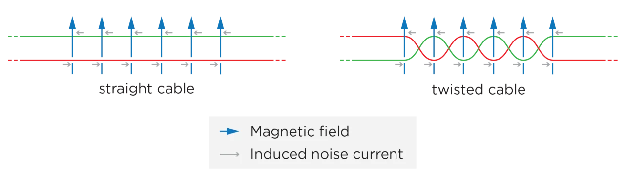
To attenuate electromagnetic interference (EMI) and noise, high-frequency data transmission via slip rings requires the pairs to be shielded and twisted.
How do I configure a slip ring?
When configuring a slip ring for optimal performance, certain fundamental issues must be considered.
First, it is essential to determine the number of power and signal circuits to be transmitted between the stator and the rotor. One must then determine the voltage, current, and type of signal (motor cable, 220V mains power, feedback, fieldbus, I/O, etc.). You can now choose the best solution in terms of contact material.
| Transmitted media | Contact material |
| Power | Silver alloy |
| <100 Mb/s signals | Silver alloy |
| 100 Mb/s signals | Gold alloy |
You must then determine the type of use for the slip ring and its application, including operating conditions, duty cycle, rotational speed, and ambient conditions (such as temperature, dust, and marine conditions). This information enables you to determine whether the joint requires protection with an application-specific coating or even a custom mechanical assembly.
The third consideration is the orientation: is the joint vertical or horizontal? The position in which the slip ring is installed will have consequences for its mechanical construction, including its bearings, housing, and so on, especially for large joints.
One must then define its size.
A reduced footprint is often a competitive advantage for the client, and it is thus important that the component be as small as possible. If a special size or shape is required, it must be specified right at the outset for inclusion in the design process.
The key factors here are the unit’s length, diameter, flange, and (optionally) through hole.