This document is for engineers, technicians, and students-thought especially for those who need, in a short time, to learn the basics about position control and position […]

This document is for engineers, technicians, and students-thought especially for those who need, in a short time, to learn the basics about position control and position sensors. The document is deliberately concise and aims to give an overview rather than cover the topic in depth.
Terminology
We engineers love technicalities-this helps differentiate us from ordinary mortals. Unfortunately, an overly technical vocabulary makes it difficult for an engineer specializing in one area to address issues unique to another. Position control is no exception, so let’s start by clarifying the terminology.
First, you will encounter various ways to refer to a “sensor”: encoder, transmitter, detector, transducer, or emitter. There are some differences, but we can consider all terms synonyms for the same object for most of its uses. We will use the universal term “sensor.”
Deceptively, some sensors, usually proximity sensors, are proximity switches from the moment they determine the presence or absence of an object. This means they generate a simple digital on/off output instead of a continuous position measurement. This paper will focus on true sensor types and not switches. In other words, sensors that generate a signal (usually electrical) commensurate with positioning along a measurement range.
Other terms refer to position (linear and rotary): dislocation, angle, angular position, rotation, rotary, and linear-again, for this paper, we will use the generic term “position” to cover both linear and angular geometries.
Almost all position sensors can also be regarded as speed sensors. Since speed can be defined as the ratio of the space traveled to the time taken to travel it, then any position sensor whose position is frequently updated is, in fact, also a speed sensor. Typical modern control systems can easily determine speed by differentiating sensor output concerning time or, more simply, by counting changes in position concerning time.
All position sensors can be classified as absolute or incremental—the output generated by an incremental sensor changes as position changes. In contrast, absolute sensors produce a signal proportional to the actual position, whether stationary or moving. An effective test to determine whether a sensor is absolute or incremental is to observe what happens when it is turned on. If there is an actual position signal without any motion, then the sensor is an absolute sensor.
Basics of position measurement
Maybe, the day they did instrumentation theory, you weren’t in class; when they explained accuracy, resolution, repeatability, and all that stuff. Don’t worry, you are in good company. Many engineers have forgotten or never really understood this topic. The terminology and the – rather esoteric – technical concepts applied to instrumentation are confusing. Nevertheless, these are important in selecting the right position sensor for your application. Get this choice wrong, and you may find yourself paying far more than you should for your position sensors; get it wrong in the other direction, and your product or control system may lack fundamental performance.
Per iniziare, alcune definizioni:
- The accuracy of a sensor is a measure of the accuracy of its output.
- Resolution is the measurement of the smallest increment or decrement in a position that the sensor can measure
- Accuracy is the degree of repeatability of the sensor.
- Linearity is the difference between the output and the actual position measured by the sensor.
We can use the analogy of an arrow shot at a target to understand the difference between accuracy and precision. Accuracy describes how close the arrow is to the center.

If many arrows were shot, the accuracy would be equivalent to the size of the grouping of arrows. If all arrows are grouped together, the grouping is considered accurate or, in other words, very repeatable.
A perfectly linear position sensor is also very accurate. For many applications, linearity can be considered equivalent to accuracy.
So it’s all clear, just put very accurate sensors to specification, and you solve every problem.
Unfortunately, there are some critical issues with this approach. First, high-accuracy sensors are very expensive. Second, high-accuracy sensors require very careful installation, which may not be easy because of vibration, different thermal expansion, or, more likely, the cost involved. Third, some high-accuracy sensors are delicate and may suffer from malfunction or failure if exposed to harsh environments.
The optimal strategy is to specify as much as necessary-no more, no less. For example, linearity will not be a key requirement for an industrial flow meter position sensor since fluid flow characteristics will likely be exquisitely nonlinear. More likely, repeatability under varying environmental conditions will be important. It should be noted that in many applications, resolution, and repeatability are often more important than linearity.
In a numerically controlled (CNC) machine tool, for example, it is presumed that both accuracy and precision are key requirements. Consequently, a position sensor with high accuracy (linearity), resolution, and high repeatability will be key requirements even in dirty and humid environments and without maintenance for long periods.
Common types of position sensors
Position sensors are used in a wide variety of industrial and commercial applications, from aerospace and defense applications to low-cost applications such as automotive and home appliances. Right after temperature measurement, position measurement is the second most important property to measure in our lifetime.
There is an amazing variety of position sensors to choose from nowadays, but how do you choose the right one? This section outlines the main types of sensors by analyzing their main weaknesses and strengths.

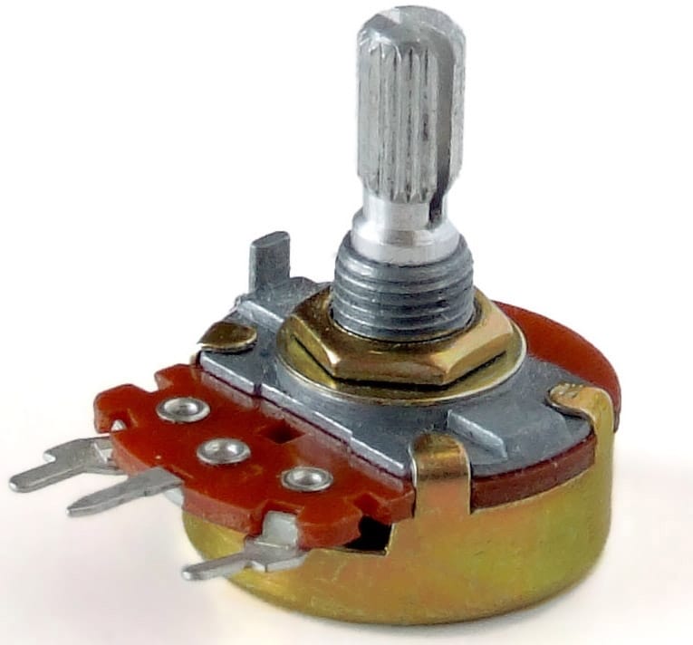
Potentiometers
Despite the trend toward contactless sensors, potentiometers (pots) remain the most common position sensors. These measure a voltage drop at the displacement of electrical contacts along the resistive trace; it follows that the position is proportional to the output voltage. Potentiometers are available in rotary, linear, or curvilinear forms and are usually compact and lightweight, ranging from a few cents for the simplest versions up to $200 for high-precision versions. Linearities of less than 0.01% are possible through laser trimming of the resistive trace.
Potentiometers are particularly suited for applications with modest duty cycles, gentle environments, and relaxed performance. Unfortunately, potentiometers are susceptible to wear, especially in high-vibration environments and/or with foreign particles such as dust and sand that would abrade the resistive trace in the long run. Higher-quality devices estimate durability in terms of the number of cycles, but the effects of vibration are often overlooked.
It should also be kept in mind that potentiometer datasheets often state “infinite resolutions.” While this is true in theory, since many control systems require digital information, the analog-to-digital converter will give the actual resolution (which must be included in the cost items).
Oddly enough, potentiometers are classified as “simple devices” in some safety-related applications in the aerospace, medical, and petrochemical industries. While they are subject to different failures, they are not subject to the same rigorous design and inspection by certification bodies as electrical sensors. It is a silly but real situation that makes replacing unreliable potentiometers in some applications difficult.
Strengths: low cost, simple, compact, lightweight, can be made accurate
Weaknesses: wear and tear, vibration, foreign objects, extreme temperatures
Further reading:
Optical Sensors
Optical sensors are usually called encoders and are a common form of position sensors ranging from simple devices costing a few euros to precision sensors costing up to 10,000 euros. All these devices are accumulated by the same principle: a beam of light is aimed through or over a grating (grating), the resulting light is measured with a photo-detector, and a position signal is generated.
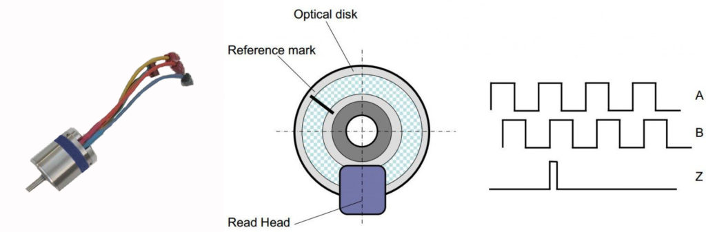
Rotary encoders are widely available, typically with 50-50,000 counts/revolution, and are tested to perform well in applications in normal environments. However, in more severe environments, the measurement will not be possible if the lens or grating system is obscured by external particles such as soil, chips, or water.
When selecting an optical sensor, it is important to know that if the quoted value of the sensor is 1,000 count/revolution, this does not mean that the accuracy is 1/1000th/revolution. It is also important to read the sensor datasheet carefully, especially with mounting kits and diskettes requiring extreme assembly accuracy to avoid contamination.
If the encoder has a glass disk, the device will have limited resistance to shock and vibration.
Punti di forza: elevata risoluzione, elevata accuratezza se assemblato correttamente, ampiamente disponibile
Punti di debolezza: corpi esterni, guasti catastrofici senza preavviso, shock, temperature estreme.
Insights:
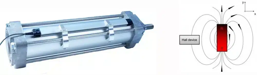
Magnetic Sensors
All magnetic sensors use a similar measurement principle: when a magnet moves relative to a magnetic receptor, the magnetic field changes proportionally to its relative displacement. A common form is Hall sensors, available in chips. They are often used for automotive and electric motor applications that require modest measurement performance.
Because of their tolerance to external bodies, magnetic sensors solve many of the problems that can be encountered with optical devices. Nevertheless, these sensors are rarely used for applications requiring high accuracy because of magnetic hysteresis and the need for precision mechanics between the rotating and static parts. Each datasheet should be read carefully in the parts on installation tolerances, temperature coefficient, and operating temperature.
An additional consideration is the proximity of magnetic materials or electric cables. Magnets may attract foreign particles, and one cause of failure is the accumulation of materials such as chips and particles over time. Usually, magnetic sensors are not the first choice for applications in harsh environments or shock conditions because of the known fragility of new neodymium (NdFeB) magnets.
Strengths: fairly robust, most liquids have no effect
Weaknesses: temperature, hysteresis, precision mechanics, nearby iron and DC sources, DC sources, and low performance for impact and shock.
Insights:
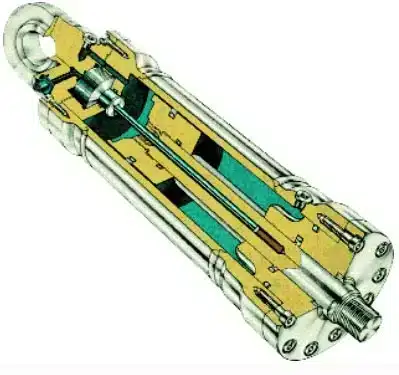
Magnetostrictive Sensors
These sensors use an uncommon phenomenon found in some materials called magnetostriction. When a magnet comes close to a material, it causes energy to pass through it to be reflected. The position can be calculated when it receives a pulse of energy to move back and forth across a strip of magnetostrictive material, usually a thin cable or strip.
Almost all magnetostrictive sensors are linear because the delicate magnetostrictive strip must be held in an “enclosure” such as an aluminum extrusion. This protection means that magnetostrictive devices do not fear wear or durability issues and can be used in high-pressure applications such as, for example, hydraulic jacks.
The manufacturer must calibrate each sensor, which, combined with precision housing, makes magnetostrictive sensors relatively expensive. This technique is also sensitive to other disturbances during time-of-flight (TOF), usually temperature.
Magnetostrictive datasheets usually estimate accuracy at a constant temperature, so engineers must consider this using estimated temperature coefficients.
The thin magnetostrictive material is delicate, and assembly on both ends is critical. We can say that magnetostrictive sensors should not be chosen for severe or vibration environments.
Strengths: robust, good for use at other pressure, accuracy rate improves with length
Weaknesses: quite expensive, shock. Effects due to temperature change, inaccurate over short distances (<100mm).
Insights:
Capacitive Sensors
A capacitor is an electronic device capable of storing charge. Typically, it has two conductive plates separated by an insulator. The amount of charge the capacitor can store varies with the size of the plates, the percentage of their overlap, and the distance and permeability of the material between the plates. In its simplest form, a capacitive position sensor measures the distance between the plates. The phase shift is typically 1mm for measuring load, strain, and pressure.
Another form is used for position sensors in which plates are cut or etched along the measurement axis. As another plate moves perpendicularly, the capacitance of the circuits across the axes changes, indicating the two parts’ relative positions. Capacitive position sensors are uncommon and rarely used in safety-related applications. Unfortunately, like plate overlap, etc., the capacitance also changes with temperature, humidity, neighboring materials, and foreign bodies, making it challenging to design a stable and highly accurate position sensor.
We have worked on sensors, automation, and electronics for almost 30 years. We have yet to meet a design engineer happy to have chosen a capacitive position sensor. Capacitive sensors have a bad reputation among experienced engineers and are unlikely to be chosen for safety-related applications. Some manufacturers have stopped discussing “capacitive,” preferring alternative terms such as charge storage, charge coupling, or electrical effects on obfuscated matter. This is not good. There are so many things that can go wrong that it is best to avoid them unless you need high measurement accuracy in very stable applications and under controlled environmental conditions.
Strengths: compact, low power
Weaknesses: high temperature and humidity coefficients, sensitivity to foreign materials, limited tolerances in installation
Insights:
Traditional inductive
Traditional position sensors base their operation on induction principles and have been used for over 100 years. They have an excellent reputation for safe and reliable operations under harsh conditions, making them an almost mandatory choice in many safety-related applications.
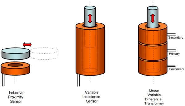
Linear position sensors are usually called Linear Variable Displacement Transducers (LVDTs). Rotary variants are known as synchros, resolvers, or RVDTs. LVDTs use the construction of a particular transformer configuration with at least three coils: one primary and two secondary. The induced signal ratio indicates the rod’s position relative to the coil. This ratio-metric technique is the key to the LVDT’s high degree of stability and measurement performance.
While optical and magnetic sensors require electrical circuits adjacent to the sensing point, induction sensors can relocate the electronics away from the sensing point, which allows the sensor to be placed in hostile environments and the electronics in more benign environments.
However, due to the construction of the transformer winding, they tend to be large, bulky, and expensive.
Strengths: high accuracy, reliability, extreme environments, widely available
Weaknesses: expensive, bulky, heavy
Insights:
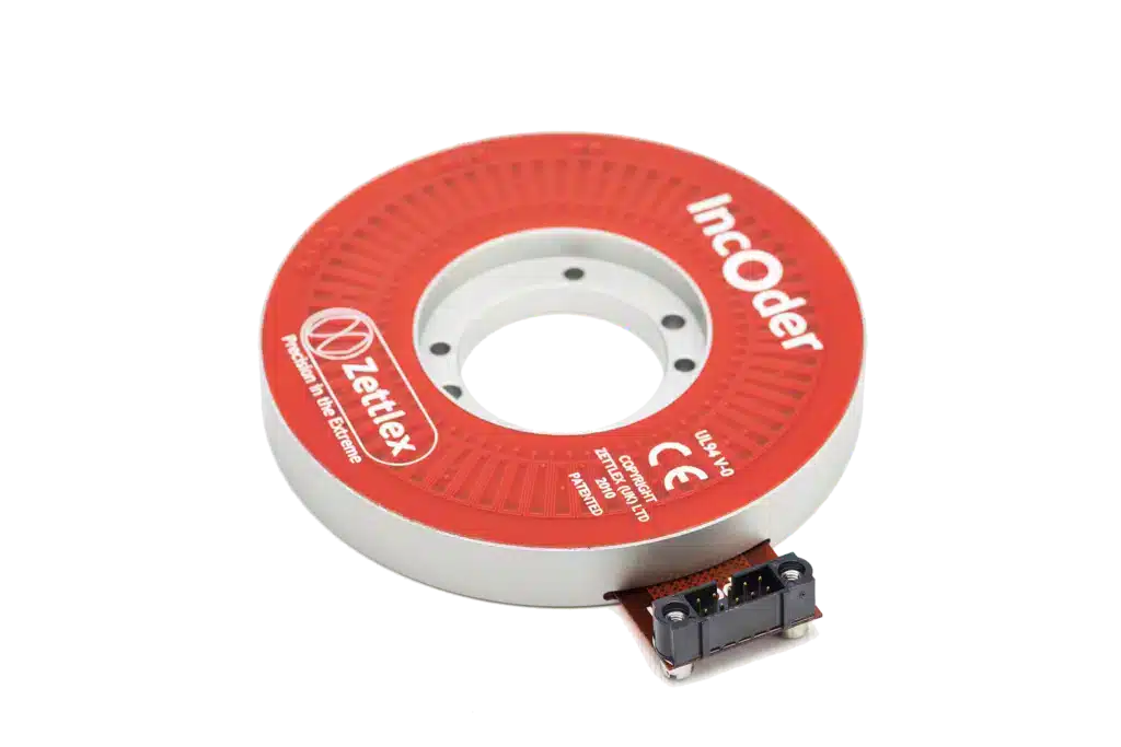
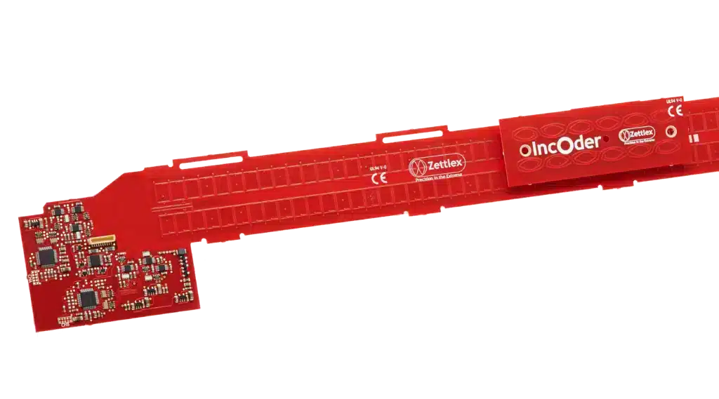
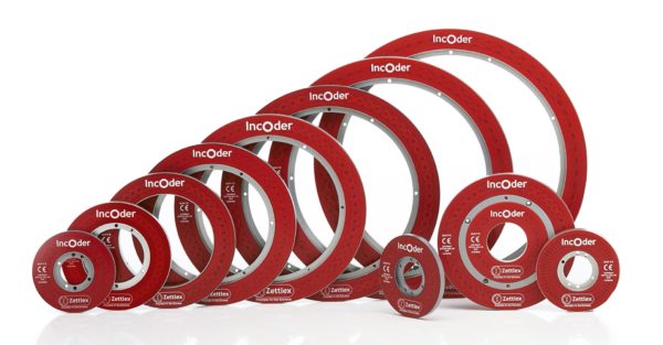
The new generation of inductive or IncOder
The new generation of inductive sensors-often referred to as IncOder-use the same principle as traditional inductive sensors, so they offer good noncontact measurement performance in harsh environments. However, these sensors use printed circuit boards on flexible or rigid substrates instead of bulky winding coils.
The switch to printed windings brings other advantages:
- A significant reduction in production costs, size, and weight
- Greater flexibility in the form
- Elimination of sources of inaccuracy inherent in the winding process
- Complex measurement geometries such as curvilinear, 2D and 3D position sensing
- Multiple sensors can be placed in the same place using a multilayer board (e.g., redundant sensors in security-related applications)
Usually, EMC performance is as good as that of resolvers or LVDTs. This is evidenced by next-generation inductive devices for aerospace and defense.
Strengths: high accuracy, reliability, robustness,
Weaknesses: more expensive than potentiometers
Insights:
Common mistakes
The list below lists the most common mistakes that engineers make related to position sensors:
Disregard the cost of sensor failure. All engineers want to choose a low-cost solution. However, this does not mean simply choosing the most cost-effective sensor. As a rule of thumb, the cost of a sensor failure in the field is bound to be a bigger and often more expensive problem than a position sensor.
In other words, selecting a sensor that will not fail in the field will always be the best cost-effective choice. In addition, there is always the nature of the failure to consider. A sensor that malfunctions and shuts down is usually better than a failed sensor that produces a wrong but credible reading. The consequences of a wrong reading in terms of cost and safety may be even greater than those of a sensor that simply stops working or gives you an error.
Do not understand the difference between repeatability, resolution, and accuracy. Reread section 3 and make sure you understand the basics. It is important to avoid the mistake (often spread by the position sensor industry itself) of confusing resolution and accuracy. Just because an encoder produces one million counts/revolution does not mean it is accurate to one millionth of a revolution. On the contrary, in many applications, repeatability is often the key requirement, and therefore, it is not necessary to specify sensors with high accuracy (=high cost).
Wrong sensor-environment combination. Humans have found ways to exploit the most basic physical phenomena to measure position through optical, magnetic, capacitive, resistive, and inductive techniques. Each technique has its strength and weakness. As a general rule, don’t pick and choose:
- Resistive (potentiometric), optical or capacitive sensors for dirty or wet environments. Condensation and surface ice in outdoor equipment are major causes of failure.
- Optical, magnetic, or capacitive sensors with extended temperature range applications (most will not operate above 125°C)
- Magnetic sensors where high performance is required, unless it is also possible to eliminate magnetic fields and arrange a precision mechanical support for the sensor.
- Potentiometers in applications with strong or prolonged vibrations. This is because its electrical sliding contacts are subject to failure and wear given by microscopic movements induced by a lot of vibration.
Derive a measurement instead of measuring directly. When designing a position sensor, measuring the position of the object you are interested in is a good idea. In other words, measure its position directly. Try not to infer or calculate the position of a component by measuring another component, such as a gear at the end of the transmission line or the position of a motor. There is likely to be backlash, gaps, part-to-part variation, mechanical failure, differential thermal expansion/contraction, etc., that would inevitably compromise the degree of performance measurement and reliability.
Forgetting cables and connectors. Cables and connectors are one of the primary causes of sensor failures. Ensure they are considered in every design and are especially relieved of strain in all applications that encounter motion, shock, and vibration.
Don’t read the fine print on the datasheet. Position sensors are a competitive industry. Unfortunately, this has made some manufacturers too clever with technical specifications. They often get away with it because many engineers will not have read a document like this. The consequence is that sensors will be advertised with, for example, a resolution of 10,000 counts/rev-without, indicating accuracy. Another example is a sensor with incredibly high resolution but much less repeatability- in other words, a lot of resolution and output noise. The trick is not to be fooled by prominent numbers in the datasheet – read the fine print.
How to choose a position sensor
The first and most important step in choosing a position sensor is to be clear about the performance you need, focusing on the values of resolution, repeatability, and linearity. Exaggerating these values will lead to the selection of an unnecessarily expensive product. The trick is finding a sensor that fits the intended use at the lowest overall cost-remembering during configuration to add a tolerance for possible field failures.
You can use the following checklist to ensure you have considered all the important aspects of your specifications. Providing this data to a position sensor manufacturer along with a technical drawing of the footprint will ensure that you lay the necessary groundwork for your discussion:
- Geometry – for example, either linear or rotary or curvilinear or 2D or 3D
- Space of the footprint – mechanical fastening points, cable routing, and encumbrances
- Type of measurement – incremental or absolute
- Full scale – for example, 360 degrees or 600mm
- Resolution – in other words, the smallest variation that needs to be measured, for example, 0.1 degrees or 0.2mm
- Repeatability – in other words, the stability of the measurement in terms of returning to the same point-for example, repeatability = +/- 0.025mm
- Linearity – the maximum deviation allowed by a perfectly accurate reading. You had better think carefully about this since we have realized that often what matters in many applications is repeatability.
- Rest and operating temperature range – -40°C +85°C is the most common
- Power supply – for example, 5V, 12V or 24V
- Electrical output – e.g., serial data, pulse, 0-10V, 4-20mA
- Uncommon things – such as “we want to keep the power consumption as low as possible” or “it is by immersion in boiling sulfuric acid,” or even “we are using a capacitive device and have reliability issues.”
Zettlex
Zettlex designs and manufactures sensors for precise position or velocity measurement in harsh environments. Position sensors use unique non-contact technology to transmit high measurement accuracy and reliability under harsh conditions. Our inductive position sensors are used for servo controls and motors, and user interfaces in medical, defense, aerospace, industrial, marine, motorsports, and petrochemical fields.