In this article, we present five things to know about slip rings (also called electric slip rings), their brushes, voltage dips, and noise attenuation. The three […]
In this article, we present five things to know about slip rings (also called electric slip rings), their brushes, voltage dips, and noise attenuation.
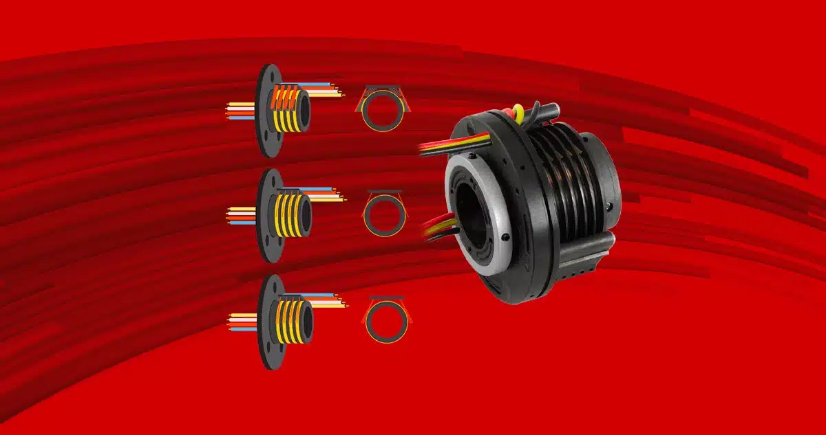
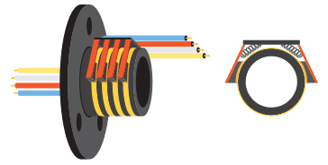
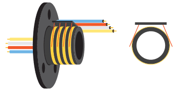
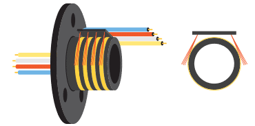
The three main technologies used for brushes in the different variants of slip rings are single-wire (single-brush), multi-wire (multi-brush), and composite.
Composite brushes are made of carbon graphite, sometimes with metals added to increase current capacity. These brushes are similar to those used in electric brush motors. Composite brushes offer excellent performance under higher current and RPM conditions.
Other brush options include monofilament, which wraps partially around the rotating collector drum at a channel and is made of precious metals such as silver, gold, or palladium. These brushes are commonly found in low-current slip rings requiring clean signal transmission and minimal contact resistance.
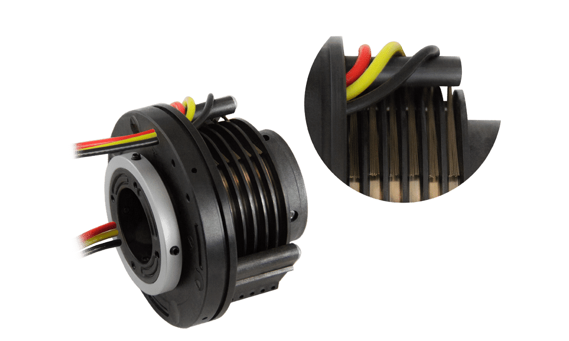
The multifilament is also made of precious metals and partially wraps around the slip ring drum but includes multiple contacts for each channel. Multifilament brushes have minimal contact resistance and noise, characteristics that make them suitable for transmitting sensitive analog signals or high-speed data for real-time control.
On a spring-loaded mechanism
2. Simpler brush-and-ring slip rings also transmit power, but the choice of brush type is critical.
Parameters indicating the most suitable choice include current, RPM, and temperature.Note: Voltage drop along the slip ring and actual current flow must also be considered in power transmission. Any drop affects the voltage available at the load–and the power dissipation within the slip ring. The latter heats up, producing a significant effect on the operating temperature.
3. Electric slip rings’ signal and data transmission speeds are steadily increasing.
How the data brushes create a variation in electrical resistance during rotation reduces the transmission quality. This variation depends on the contact mode of the brushes and force, rpm, and temperature. One solution for advanced applications is to use multiple contacts for each channel as the poly filament brush type-to reduces this resistance variation.
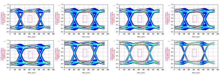
Bit Error Rate (BER) expressions quantify the noise and reliability of data across a slipstream. Pictured: Keysight Technologies’ DDR Bus Simulator generates bit error rate (BER) profiles to quantify reliability. To learn more about this topic, visit testandmeasurementtips.com or keysight.com (ENGLISH).
Regardless of brush shape, speeds and capacities are key parameters in transmitting slip ring signals. Many Ethernet-connectivity products transmit signals and data at up to 10 gigabits (Gbit or simply Gb) per second or higher. Commonly available products currently exceed 1 Gb (a fairly standard benchmark), although slip rings with this transmission rate still represent specialized solutions.
Of course, vendors point out that most OEMs do not need 1 Gbit and that 100 megabits (Mb) per second is sufficient. However, as the number of sensors increases and designs using slip rings become more complex, Gb speeds-in many cases in Gigabit Ethernet (GbE or GigE)-will increasingly be the standard.

Note: Besides signal transmission, data movement through a slip ring is a common distinguishing feature among manufacturers. This data movement sends high-frequency information for higher-level controls and operational functions–often via Ethernet or one of the derived protocols, such as PROFINET or EtherCAT.
Many of these protocols enable the control of various machine subsystems, support IIoT functionality, and enable the use of all data from sensors proliferating on machines. Eventually, their deployment will require more (and faster) data transmission through slip rings.
4. Data transmission through electrical slip rings requires shielding and attenuating electromagnetic interference (EMI) and noise.
EMI attenuation is sometimes expressed as electromagnetic compatibility or EMC. Data transmission requires slip rings with higher bandwidth and better EMI attenuation than power transmission. EMI often travels through conduction and radiation. The former takes the form of harmful high frequencies that occur along the power line supply or signal. Conversely, radiated EMI propagates electromagnetic noise through space to nearby equipment. Shielding slip ring connections against such EMI is of paramount importance. Note: Radiofrequency (RF) shielding is another common feature in slip-ring connections. Although they are used interchangeably, the terms EMI and RFI have different meanings. More precisely, EMI represents any frequency’s electrical noise, while RFI is between 20 kHz and about 300 GHz.
5. Data transmission through electrical slip rings also requires grounding.
Suppose a designer or OEM has a large electric motor that rotates the axis of a machine. This motor will have a transmission, such as a VFD, that generates a large amount of electrical noise. If there are nearby slip rings without proper grounding, this noise will affect them; the interference originating from the motor’s transmission will couple with the slip ring traces and introduce interference on communications or signal lines.
For projects where EMC is a design objective, an all-metal box with the dedicated ground and shielded-only cables can mitigate most EMI.Note: These preventive measures become more critical as data rates increase. This is because, as frequencies increase, the data signals on the wires from the slip rings become emitters at some point.