The Motion Controller The motion controller is the “mind” of any motion control system. In feedback systems, it sends a command toward the drive, compares it […]

The Motion Controller
The motion controller is the “mind” of any motion control system. In feedback systems, it sends a command toward the drive, compares it with the motor’s feedback signal, and introduces the corrective action necessary to align the output signal (desired position) with the input signal (current position), ideally with minimal error.
The motion controller also defines the motor’s trajectories to accomplish the input commands. It is also known as a motion profile, where profile means a time-dependent sequence of position commands that tells the motor where to place the load and with what speed. The motion controller uses the created trajectories to generate appropriate torque or velocity commands, which are then transmitted to the drive that drives the motor.
Because of the large volume of data to be processed, the motion controller uses a digital signal processor (or digital signal processor, hence the acronym DSP) for this function. DSPs are specially designed to perform mathematical operations quickly and efficiently and are better able to handle algorithmic processing.
Numerous common motion profiles exist, including trapezoidal, ramp, triangular, and complex polynomials. Each is employed under certain conditions and situations requiring that type of motion. For example, a trapezoidal profile is characterized by constant acceleration, velocity, and deceleration; the velocity graph has a trapezoidal shape as a function of time.
Motion controllers use the error signal between the current position and the commanding position to make appropriate corrections to the signal sent to the driver. The simplest is proportional control (P), which expresses a gain proportional to the error. Normally a derivative action (known as D) or an integral action (I) is added. The combination thus obtained, known as PID, constitutes one of the most common and efficient control algorithms.
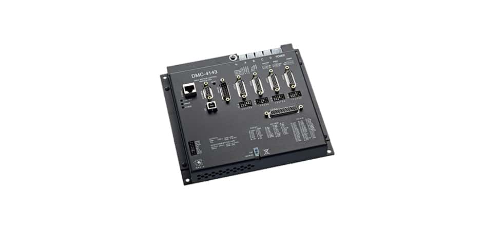
From a practical point of view, motion controllers of various sizes and types are available. They generally fall into three categories: stand-alone, PC-based, and single microcontrollers.
In the first case, these are stand-alone systems mounted in a cabinet, including all the necessary electronics, power supply, and external connections. This type of controller, which can be integrated into a machine, is dedicated to a single- or multi-axis motion control application.
PC-based controllers are installed in the motherboard of a regular or industrial PC. They are essentially processing boards capable of generating and executing motion profiles. The advantage of PC-based controllers is the ready-to-use graphical user interface, which greatly simplifies programming and adjustment.
Finally, there are microcontrollers, with feedback input from the motor and output to the driver. While this type of controller is relatively cost-effective, offering designers access to the system at the firmware level, it can require good programming skills for configuration and implementation.
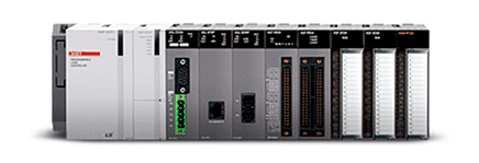
PLC
PLCs (Programmable Logic Controller) are highly specialized microprocessor-based programmable controllers used to manage a specific application on a machine or process. They are used in automation and manufacturing to control assembly lines, factory machinery, and many other mechanical, electrical, and electronic plant equipment types.
The basic components of the PLC include the processor, I/O modules for processing input signals to the controller and output signals to the controlled devices, and any type of user interface, which may simply consist of a keyboard, touch screen, or PC programming link. The PLC processor is programmable through the user interface. I/O modules transmit input signals to the PLC CPU and output signals to the controlled devices, which may consist of motors, valves, sensors, and actuators.
One final note: An important aspect of any PLC is the scan time, which is the time it takes the PLC to execute the program by receiving input data and updating output data. It generally does not exceed a few milliseconds but can take much longer depending on the program’s length and the processor’s speed. Extended scan times can handle processes with higher real-time demands than slower traditional applications where scan speed is not critical.