Through-bore slip rings are critical electromechanical components used to transmit power and data across a rotating interface while allowing a continuous hole (or bore) through the […]
Through-bore slip rings are critical electromechanical components used to transmit power and data across a rotating interface while allowing a continuous hole (or bore) through the center of the assembly. This design enables engineers to pass with optical channels, route shafts, fluid lines, or other mechanical elements directly through the middle of the slip ring, making them a versatile solution in countless industrial and automation applications.
Unlike traditional capsule slip rings that feature a closed housing, through-bore designs center around a hollow shaft construction. Conductive rings are mounted around the bore, and brushes maintain electrical contact as the assembly rotates. This arrangement provides both electrical continuity and mechanical flexibility, enabling a wide range of machine designs that require simultaneous rotation and unobstructed axial space.
How Through-Bore Slip Rings Work
At the heart of a through-bore slip ring is a matched pair of conductive rings and brushes: one set rotates (either the rings or the brushes), while the other remains fixed (or rotates more slowly). The conductive rings are typically mounted concentrically around the bore, and the brushes maintain sliding contact with them to transfer electrical signals or power across the rotating interface.
This configuration allows uninterrupted 360-degree rotation while carrying a mixture of electrical circuits, power, analog signals, digital data, or even high-speed Ethernet, without twisting or tangling cables. Engineers can run mechanical components such as hydraulic lines, pneumatic channels, or drive shafts directly through the center, eliminating the need for complex cable management systems.
Key Applications
The versatility of through-bore slip rings makes them indispensable across multiple industries:
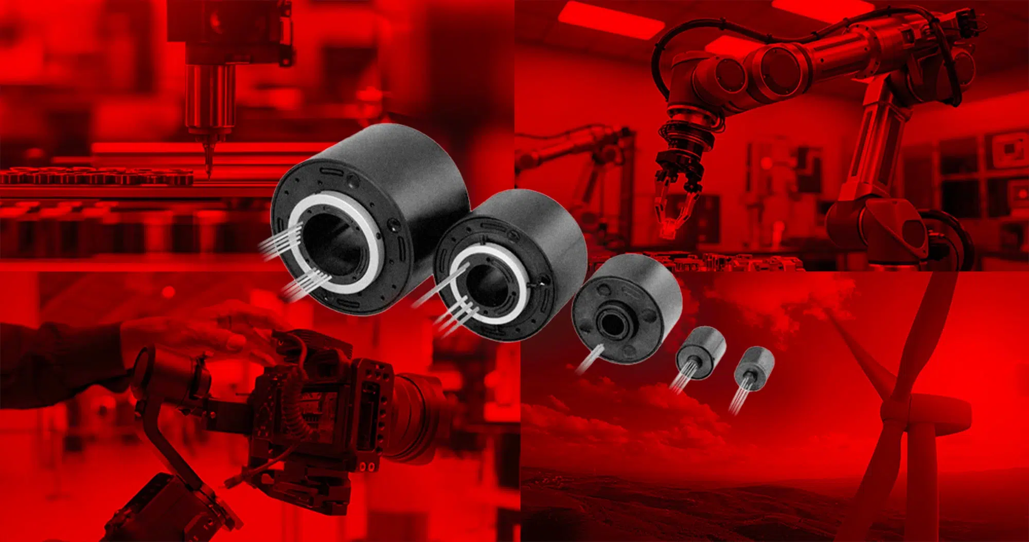
- Robotics and Automation: Robots often require continuous rotation of joints or end-effectors while transmitting power, control signals, and sensor data. Through-bore designs allow robot axes to rotate freely while housing actuators or gear shafts in the center.
- Wind Turbines: Pitch control systems and nacelle yaw mechanisms benefit from the central bore, which can accommodate drive shafts or hydraulic lines while providing electrical connectivity for sensors and control systems.
- Medical Equipment: CT scanners and advanced imaging systems rely on uninterrupted rotation for high-resolution imaging. The through-bore allows unobstructed passage for patient tables, cabling, or cooling lines while maintaining reliable data and power transfer.
- Packaging Machinery: Automated packaging systems that feature on carousels often combine rotating assemblies with pneumatic or hydraulic lines. Through-bore slip rings provide the necessary electrical pathways while allowing air or fluid delivery through the center.
- Industrial Gimbals and Cameras: Precision camera systems and antenna arrays require smooth rotation with minimal electrical noise. Through-bore designs accommodate support shafts or optical components while ensuring uninterrupted data transmission.
These examples highlight why engineers value the ability to combine electrical transmission with a clear mechanical pathway through the core of the slip ring.
Engineering Considerations for Selection
Choosing the right through-bore slip ring requires careful evaluation of both electrical and mechanical requirements:
Bore Size
The central bore must be large enough to accommodate shafts, fluid lines, or other hardware. Common sizes range from small diameters for compact sensors to large openings for heavy-duty industrial equipment.
Circuit Configuration
Engineers must specify the number and type of circuits—power, signal, or hybrid. Mixed-use designs can combine high-current power circuits with low-voltage signal lines, but each circuit type requires careful isolation to avoid interference.
Bandwidth and Data Transmission
Applications involving Ethernet, fieldbus protocols, or high-speed digital signals demand low electrical noise and optimized contact materials. Factors such as impedance, shielding, and contact resistance directly influence performance.
Protection and Environment
Ingress Protection (IP) ratings determine how well the slip ring resists dust, moisture, or other contaminants. Harsh industrial or outdoor environments may require sealed housings, special coatings, or corrosion-resistant materials.
Brush and Ring Materials
Material choice—gold, silver, graphite, or specialized alloys—affects contact resistance, wear rate, and signal integrity. High-speed data applications typically require precious-metal contacts to reduce noise and maintain consistent conductivity.
Mounting and Integration
Through-bore slip rings can be designed for shaft mounting or flange mounting. Proper alignment and torque control are critical to minimize wear and extend service life.
Lifecycle and Maintenance
Brush wear is a natural consequence of continuous contact. Selecting a model rated for the application’s duty cycle, rotational speed, and maintenance schedule ensures long-term reliability.
By balancing these factors, engineers can select a through-bore slip ring that meets electrical requirements without compromising mechanical integration.
Example of a Modern Through-Bore Solution
A contemporary example of this technology is Servotecnica’s SVTS C Series, a through-bore slip ring engineered to handle a broad range of signal and power requirements. It illustrates how modern designs can achieve high circuit density, low electrical noise, and flexible mounting options, all within a compact footprint.