Through Servotecnica’s catalog, one can find motion control solutions among the most diverse analog controllers, with Ethernet protocol and EtherCAT solutions. Choosing which path to take […]
Through Servotecnica’s catalog, one can find motion control solutions among the most diverse analog controllers, with Ethernet protocol and EtherCAT solutions. Choosing which path to take sometimes becomes difficult, given the overlap between the various solutions. We want this presentation to provide indicative basics of choosing without claiming to have identified all possible solutions.
Bearing in mind that systems are increasingly complex and need to exchange information between elements of the same machine and between components sometimes located far apart, an initial demarcation must be made between controllers with Ethernet protocol and others with EtherCAT protocol.
Ethernet Communication
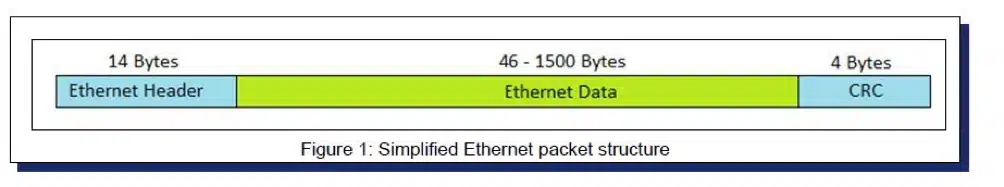
The main purpose of Ethernet communication is data integrity and the amount of data transmitted in the unit of time, aka “throughput.” Data are transmitted in objects called packets. Each data packet contains fields such as source address, receiver address, and information being exchanged, i.e., “payload data” or “Ethernet Data,” etc. The data contained in the “Ethernet Data,” see Fig. 1, can be of different sizes depending on the protocol type. Being able to reach 100 Mbit/sec as transmission speed, it could be defined that an Ethernet network represents practically instantaneous communication.
The term “practically” is to be used since, in Ethernet communication, all components are receivers and transmitters, they can cause data overload that can cause intermittent and unpredictable delays if packets are lost or due to possible collisions. These events can be minimized but not completely eliminated. Should they occur, the communication delay would exceed one millisecond, which is unacceptable for a motion controller. For this reason, Ethernet communication is defined as nondeterministic since it does not guarantee that information can reach its destination in a defined and constant time.
Analogue Controls
A block diagram of a system using a PC and a motion controller is shown in Fig. 2. It can be seen that Ethernet communication is restricted between the host and the motion controller. At the same time, between it and the drivers is done by employing the +/- 10 VDC analog standard. The real-time motion profile, Inputs, Outputs, and PID filter are in the motion control. Since the I/O commands, the analog signal is transmitted through copper electrical connections, the delay between sending and receiving the command is practically zero. Non-real-time communication is only between the Pc and the motion controller.
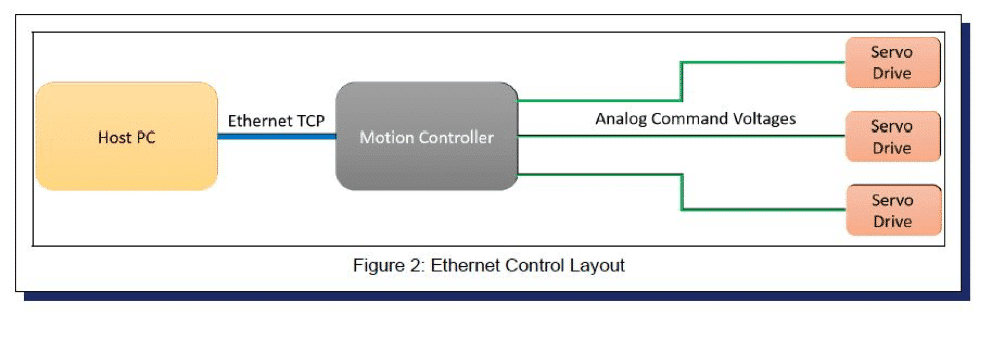
We can therefore assert that an analog motion controller inherently has a deterministic solution.
EtherCAT Communication
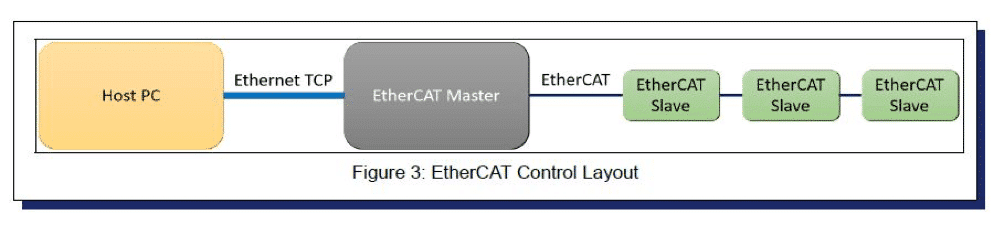
In an EtherCAT solution, communication between Host PC and EtherCAT Master is not critical. The motion profile and I/O commands are generated by the EtherCAT Master as a block diagram in Fig. 3. Compared with the previous solution, the motion command between Axis Control and Drivers, instead of being via an analog signal, is via 32 bits for a commanded position or 16 bits for the current command.
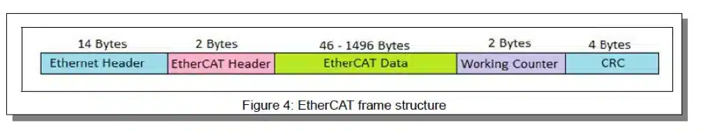
Data is transmitted in a packet with a structure similar to that used in Ethernet communication see Fig. 4., likewise the encoder and I/O signals return to the EtherCAT Master. This occurs in a regular time interval known as the EtherCAT Cycle Time, typically 1 msec but can go down to 0.1 milliseconds.
If EtherCAT employs the same packet structure as Ethernet and the same electrical connection, how do we make up for potential problems due to communication uncertainty? The difference lies in the high degree to which EtherCAT communication is coordinated and structured, plus two EtherCAT transmitters cannot exist in the same network; all this eliminates the possibility of having collisions during transmission. Each element is equipped with an ASIC that allows each to directly take information from the EtherCAT packet by mapping it into memory and sending its own information back into the same packet; this data is used either in the motion profile or in the ‘position register update depending on the mode of operation. This direct way of receiving and sending data minimizes delay by enhancing the EtherCAT system’s ability to process information at an unmatched speed, even by analog systems. All these advantages come at a cost. The network must be set up via software before it is deployed. Each EtherCAT Slave must be configured to take charge of only one sector of bytes within the packet. The EtherCAT network must be closed, making it incompatible with the Ethernet standard if it employs switches or hubs. Lastly, using an ASIC also for I/O or analog signals and servo drives means an increase in cost compared to analog motion controllers. It is also true that the number of EtherCAT axes is continuously increasing, so the cost gap will be getting smaller and smaller in the near future.
Centralized or distributed controls
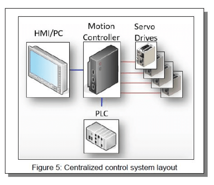
A centralized system consists of a motion controller responsible for coordinating axis motion, managing I/O, and communicating with a PC host or HMI. A typical example is a CNC machine, shown in blocks in Fig. 5. There are at least 4 axes, numerous I/Os such as limit switches, probes, and a PLC can coexist to handle additional I/Os. All input information and output commands are processed by a single control coordinating actions within milliseconds. In this system, a clock ensures that feedback from the motors and commands to the drivers are processed in real-time, therefore with the certainty of sampling time in a deterministic manner.
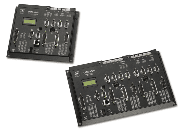
A typical example of centralized control can be found in the figure below, these are the 4- and 8-axis Galil DMC-40×0 series controllers, in the same enclosure, are housed up to 8 drivers suitable for driving motors up to 1.2 Kw brushless, brush or stepper increasing the speed of execution, avoid electrical interference, and to keep costs down. In the solution without integrated drivers, any driver can be used. Servotecnica proposes Mecapion drives powered directly from the mains with small dimensions and costs or towards the Ingenia family of drivers.
A second opportunity comes from using LSIS controllers and their respective drivers. The controller interfaces to HMI via high-level protocols but could be an Ethernet protocol interface while sending motion commands via EtherCAT protocol.
Similar to this solution is now available the first GALIL EtherCAT controller that can manage up to 32 Slaves in addition to 2 EtherCAT IO modules
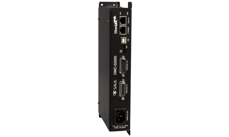
Matching toward the drivers we propose are always Mecapion drivers with mains power or Ingenia drivers.
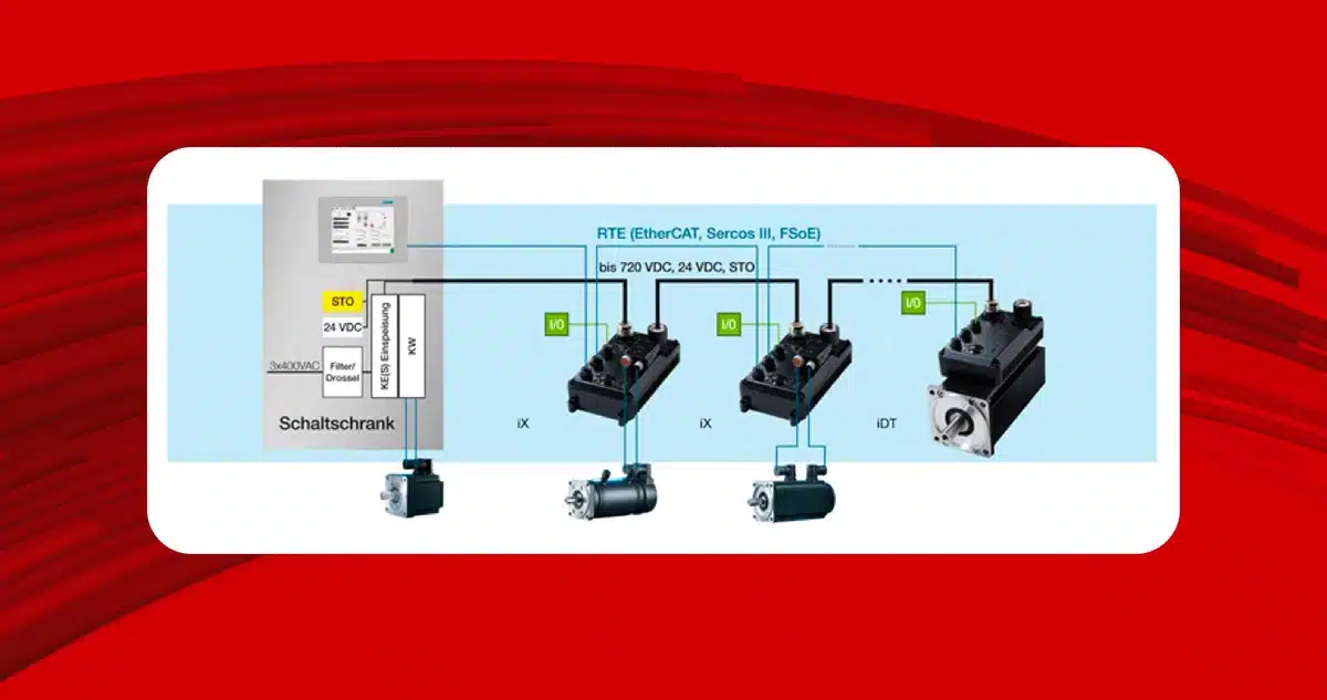
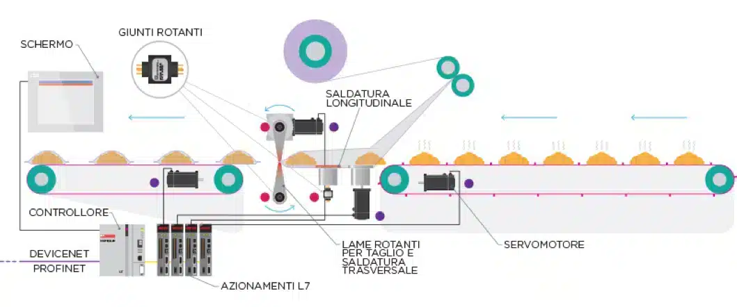
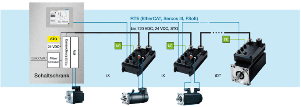
The decentralized solution should be considered the best when the system develops with a certain length or with many axes. It allows a strong reduction of wiring time and a drastic decrease in introducing electromagnetic disturbances via electrical cables; also, given maintenance optimization, they are preferable to centralized systems.
In the figure below, motion controllers and PLCs exchange information via a fieldbus, typically Ethernet. Deterministic controls such as IO and motion are handled locally. Each node consists of a master that sends commands and monitors the status of the various electronic components. The benefit is that each control is employed for a specific function, greatly improving processing times by allocating specific resources to process processes that must prioritize execution over others.
Determinism
Employing hardware with a defined clock and interrupt rather than synchronization via EtherCAT cycle time, we operate with deterministic solutions in both cases. It is often assumed that since EtherCAT is a deterministic protocol, it must be used exclusively when these functions are required. To clarify, in both cases, whether an analog control or an EtherCAT Master is employed, the same results are obtained. For each system, the decision between centralized or distributed motion control depends on how the system develops, where actuators and motors are located, and the distance between controllers and these elements both need to be covered with cables to reach the various components.