Encoders Optical encoders have been the preferred choice of machinery manufacturers since the 1970s. Many manufacturers distribute them and find their way into various industrial machines […]
Encoders Optical encoders have been the preferred choice of machinery manufacturers since the 1970s. Many manufacturers distribute them and find their way into various industrial machines such as printers, CNC machine tools, and robots. Traditional inductive position sensors, such as resolvers or LVDTs, date back to the 1940s but are less widely used. They are a viable alternative in harsh environments, such as aerospace, defense, and petrochemical applications. Their robustness and reliability make the high cost accept the higher weight and mass compared to optical solutions. However, a new type of inductive sensor is gaining market share in many areas, we are talking about “incoders,” which can be considered a hybrid technology between optical and inductive. With so many different technologies available, it is not easy for the designer to make a thoughtful choice. This article compares optical and inductive encoders by examining their merits and weaknesses.
What is an Encoder?
A definition of this component should first be given. An encoder is a device that converts position or motion into an electrical signal, usually with a digital code. There are many definitions we talk about rotary encoders, angle encoders, angle sensors, and angle transmitters. To simplify, we will use the term encoders, which can be rotary or linear.
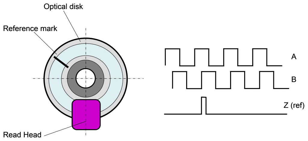
An important distinction is whether the encoder is absolute or incremental. In an absolute encoder, the electrical signal indicates an angular or linear position immediately after it is turned on. Incremental encoders only provide information if there is motion. Some incremental encoders also provide a reference signal, called Index or Home, which is used as the datum from which to start increments or decrements in shaft position.
Incremental encoders are more widely used than absolute encoders, although this trend is being reversed, especially in new applications. In many areas, such as robotics and automation systems, it is preferred to have the position already in the power-up phase without providing a position zeroing routine by going to a reference point, which involves the movement of the axis concerned.
The electrical signal generated by incremental encoders is two A/B signals. This refers to 2 or more low voltage signals in quadrature with each other that change state from high to low as the position changes. The direction of motion is determined by the flow of the A signals concerning B if they are leading or lagging. The most common communication protocol for absolute encoders is SSI (Synchronous Serial Interface), which indicates absolute position through a digital bit communication.
What is an Optical Encoder?
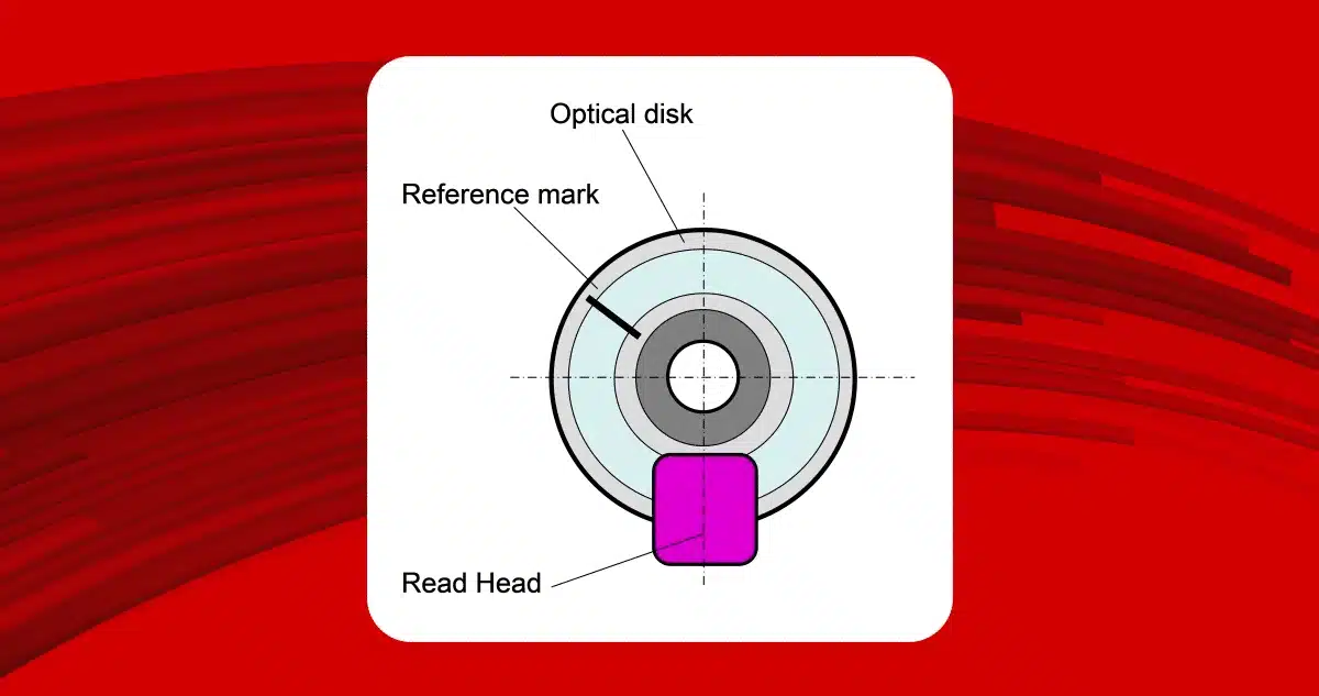
In un encoder ottico è presente una sorgente luminosa che trasmette la luce verso un disco che presenta delle aperture che permettono il passaggio della luce e lo impedisce se non c’è apertura. Queste aperture o chiusure vengono chiamate “grating”o “griglia”. Un rilevatore ottico opposto al trasmettitore rileva la presenza o l’assenza di luce e genera un segnale elettrico corrispondente. Grazie alla griglia si determina lo spostamento angolare e se l’albero dell’encoder è in movimento e in quale direzione. Si possono arrivare a griglie con marcatura moto piccola, fino al micron, consentendo misure con elevato grado di precisione.
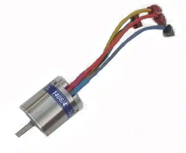
Normally, the encoder shaft is mechanically connected to the moving part of the machine. The encoder shaft has support bearings and carries the optical disk interposed between the emitter and detector. The electrical connection is via a multicolor cable that provides DC power and carries the encoder position output data. The simple electrical interface combined with easy availability makes them easy to deploy. The weak point is sensitivity to vibration, shock, foreign materials, and extreme temperatures. There is no warning of an impending error, which can cause incorrect position reporting, which can cause significant problems for the equipment. When the diameters are large, ring encoders are used; in this case, the tolerance between the optical read head and the grid has very tight mechanical tolerances, which makes them very sensitive toward dust or dirt particles. These factors discourage using optical encoders in systems requiring high reliability and safety.
- Strengths: High resolution, widely available, high accuracy
- Weaknesses: delicate, sensitive to external contamination, possibility of significant failures, limited temperature range (-20°C to +70°C)
What is an inductive encoder?
An inductive encoder, often called an encoder, uses inductive principles to measure the position of a rotor relative to the stator. Incoders are mechanically comparable to resolvers or LVDs, their electrical interface is similar to an optical encoder with a simple power supply and digital output signal.
Many conventional resolvers are like electric motors with copper windings on the stator and a metal rotor. The inductive coupling on the stator windings varies according to the position of the rotor. Instead of employing a construction technique such as that used in transformers, Incoders use printed circuit boards for the stator and rotor, making them less bulky, more accurate, and less expensive to manufacture.
Resolvers and LVDTs have proven their reliability, accuracy, and robustness over time and thus are often used in high-reliability and safety applications. Incoders are just as easy to integrate as optical ones, requiring only a DC power supply and providing a digital output signal representing position. This allows them to be compared in terms of advantages to resolvers without disadvantages.
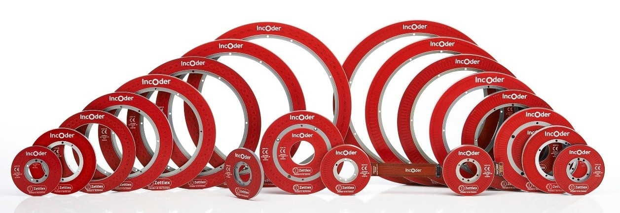
Since Incoders do not use optical components, they are not sensitive to foreign materials and have no limitations due to temperature. In addition, position measurement does not require mechanical assembly with high tolerances between the stator and rotor parts. Since they do not require bearings, very thin rings with a large through-hole are obtained, which, with their low weight, make them an extremely high-performance solution in rotary joints, robotic arms, and actuators.
- Strengths: High resolution, accuracy, reliability, robustness, long service life, tolerant to misalignment
- Weaknesses: extended temperature range (-100°C + 125°C)*
*Wider than optics but not as much as resolvers