This paper describes the synchronous serial interface (SSI) used in many position sensors and controllers. It is intended for electrical and mechanical engineers who design position […]

This paper describes the synchronous serial interface (SSI) used in many position sensors and controllers. It is intended for electrical and mechanical engineers who design position sensing systems and wish to understand how the SSI interface works and how to evaluate its benefits without going into too much detail.
Introduction
Sensors that measure linear or angular position can be divided into two groups: incremental and absolute. The question “What happens when you turn it on?” is a good reference point for determining which group a sensor belongs to. If the sensor has to perform a calibration step to find its position, it is incremental; otherwise, it is absolute. Most engineers’ specifications still include incremental position sensors because absolute ones are considered too expensive. However, today absolute sensors no longer cost that much more. Because users of automation equipment and systems are no longer willing to accept long start-up times, the number of absolute sensors is increasing.
In the 1980s and 1990s, many absolute position sensors generated a parallel output. The ones and zeros of a binary value or Gray code were represented by several wires (often a ribbon cable) with a high or low logic level. This approach has disappeared because of its relatively high cost, size, complexity, and reliability, especially in precision sensors. A sensor with a 20-bit parallel output would require at least 20 separate signal wires. While not a big problem in the case of a single sensor, this configuration becomes a nightmare, for example, for a robot, where sensors, motors, and power lines are numerous.
General elements of the SSI interface
The SSI is based on the widely used RS-422 hardware standard. In this standard, the electrical characteristics of signaling circuits are specified, limited to the definition of signal levels. In other words, the basic hardware is defined, while other specifications, such as electrical connectors, pins, and wiring, can be freely chosen by the designer. The RS-422 circuits employed by the SSI interface allow data to be transmitted reliably and quickly over long distances and in noisy environments without the need for bulky electronics, cables, and connectors. Balance or differential signaling can achieve high data rates and long distances. Differential means that when one line is on the high level, the other is on the low level, and vice versa.
SSI can be described as … deep breath … a serial synchronous end-to-end communication channel for digital data transmission. Phew. “End-to-end” is not a complex multi-node bus or network system. “Synchronous” means that a clock signal synchronizes data transmission. “Serial” means that it is not parallel; therefore, multiple data bits are sent on the same wire. Data transmission occurs between a “master” (usually a controller) that sends the clock signal and a “slave” (usually an absolute position sensor) that generates the data or value.
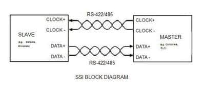
RS-422 uses nominal signal levels from 0 to 5 V and typically a cable consisting of two sets of twisted pairs (one for data and one for clock signals) and a ground wire, as shown in Figure 1. While a cable with two pairs may be a practical solution in many RS-422 applications, the specification only defines the signal path without assigning any function. Most SSI cables use twisted pairs with a metal foil or mesh acting as an electromagnetic shield on each pair and/or the entire bundle under the general cable jacket.
Usually, with SSI, data and clock transmissions over cable lengths around 20 m do not require special arrangements. Distances of 20 m meet the needs of most position sensor applications. With cable lengths greater than 20 m, cable lengths between the position sensor and controller should be reduced to the minimum possible. While high data rates of about 10 Mbit/second can be achieved without difficulty with cables of 10 or 20 m (24 AWG), for lengths greater than 20 m, it is necessary to reduce sensor data rates, as shown in Figure 2.
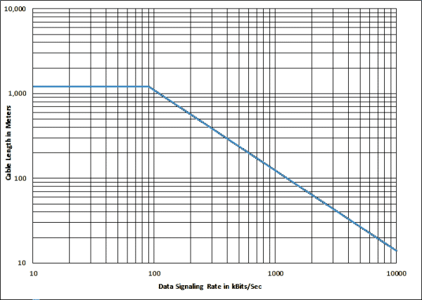
The above data are based on 24 AWG wires, and cable lengths may be longer for 22 or 20 AWG cross-sections. The maximum cable length depends on tolerable signal distortion, local electromagnetic noise levels, and ground potential differences between the cable ends.
Compared with other interfaces, the technical features of SSI are:
- Low cost due to:
- Reduced number of electronic components
- only 4 wires
- Slaves or sensors that use the clock of the master and do not require precision oscillators
- the wide availability of connectors and cables
- Secure data output with the ability to detect errors and report parity
- resilience to electromagnetic interference
- possibility of using cables of considerable lengths up to thousands of meters
- easy electrical isolation between the sensor and host
- Data transmission is synchronized with a clock signal.
- high baud rates up to 10 Mbit/second
- a specific message size does not limit the flexibility-the number of bits in a message
- Ability to connect multiple slaves to a standard clock.
Sometimes engineers get confused between SSI, RS-422, and RS-485. SSI is the serial communication method that uses RS-422 hardware standards. RS-485 is a more complex multi-node system or bus. RS-422 does not allow a true multipoint communication network to be implemented because there can only be one driver in each wire pair; despite this, multiple sensors can use the same clock signal.
SSI clock and data transmission
The master (or controller) controls the clock signals, and the slave (position sensor) transmits the data or value. When recalled by the master, the data is output by the slave at the clock cadence and is usually stored in a shift register. The clock synchronizes master and slave. Data are transmitted using balanced or differential signals. This means that the CLOCK and DATA lines are twisted pair cables. The clock sequence is initiated by the master when data or value is needed. Different clock frequencies ranging from 100 kHz to 2 MHz can be used, and the number of pulses depends on how many bits of data need to be transmitted. The data transmission protocol is based on three different successive parts (“1″ start -> data bits -> “0” end). This achieves reliability and security of data transmission without hardware and software errors.
The SSI is initially in idle mode, in which the CLOCK and DATA lines remain high, and the slave continues to update its data. By keeping the CLOCK and DATA outputs in idle mode at a high level, contacts caused by broken wires can be detected.
As can be seen in Figure 3, the first falling edge after time Tmu starts the read cycle and data transmission. Each rising edge of the CLOCK transmits the next data bit of the message starting from Dn-1. After the last rising edge of the clock sequence, the data line is set by the error flag (if supported) for the period Tmu – 0.5xt. At the end of Tmu, the last position data is available for transmission in the next read cycle.

- T: a period of the clock (1/T = from 100 kHz to 2 MHz)
- Trc: read cycle time. It is defined as (n x T) + (0.5 x T)
- Tmu: message update time. The time interval from the last falling edge of the clock to the time when new data is ready for transmission
- Timg: time between messages. Must be >Tmu; otherwise, the position data will be indeterminate
- n: number of bits in the message (error flag not included).
After n CLOCK pulses (rising edges), the data value is transmitted. The sensor output goes low at the next CLOCK pulse (n+1 rising edge). The interface is short-circuited if it is on a high level even after n+1 rising edges.
Through connection to a common clock, readings from multiple slaves (up to three) can be taken simultaneously. To avoid ground loops and electrically isolate the slave, complete galvanic isolation by photocouplers is required.
Multiple transmission of the same data from the position sensor occurs only in the case of continuous clock pulses, even after transmission of the least significant bit. The initial sequences are the same as for single transmission. In the idle condition, the CLOCK and DATA lines are high. When the first falling edge arrives, the transmission mode is invoked. The data bits are similarly transmitted in sequence, beginning with the most significant bit at each rising edge of the CLOCK. The transmission of the least significant bit indicates that all data has been transmitted. A further rising edge brings the data line to a low level, indicating the end of data transmission.
Suppose continuous clock pulses are present even after the end of transmission (i.e. if subsequent clock pulses arrive within time tw [< tm]), the value of the slave is not updated. This is because the monostable output is still unstable, and the value in the shift register has not changed. Therefore, at the next rising edge, that is, after the rising edge (n+1), the transmission of the same data continues, and the MSB of the previously transmitted data is retransmitted. Then the same procedure as the previous transmissions is followed, resulting in multiple transmissions of the same data. The slave value is updated only when the time between two clock pulses is longer than the transmission timeout. Multiple transmissions can be used to verify data integrity. The two consecutive values received are compared, and any differences found indicate transmission errors. The master controls data transmission and can be interrupted at any time simply by interrupting the clock sequence for a period longer than the timeout period. The slave automatically recognizes the transmission timeout and goes into idle mode.
Some manufacturers of position sensors have added additional information to the basic SSI protocol to ensure high integrity of data transmission. To ensure security and signal the end of data transmission, CRC or parity bits can be added, which are used to verify whether data from the position sensor has been correctly received and interpreted.
Sensors using the SSI interface
Attentive readers may have noticed that the term “sensor” is used in this article instead of the more common “encoder.” This is an intentional choice because encoders are often, but erroneously, thought of as optical devices that generate data as a function of a measured position. In recent years, a new generation of non-contact (mostly absolute) encoders has emerged that is not optical but inductive (also called “incoders”). Such devices use printed-circuit transformers instead of the bulky and expensive windings used in traditional inductive position sensors, such as resolvers, LVDTs, RVDTs, and synchronizers. These traditional devices have been the preferred choice of engineers for many years for various harsh environments because of their reliability, high degree of safety, and non-contact mode of operation. Incoders are based on the same principles as their traditional counterparts, making them as reliable and robust as they are more accurate and easier to use. The ease of use stems partly from the use of the SSI interface as their preferred mode of communication. They have gained significant market share in through-hole and bearingless versions in applications where sensors with high reliability and accuracy are needed in the medical, industrial, aerospace, and defense sectors.