The term “moment of inertia” is often used with a generic meaning but, depending on the context, can denote three different moments of inertia: mass, planar […]
The term “moment of inertia” is often used with a generic meaning but, depending on the context, can denote three different moments of inertia: mass, planar or polar. To know which of these values is necessary for a given calculation or analysis, it is important to understand how they differ and their relationship to an object’s behavior.
Mass moment of inertia
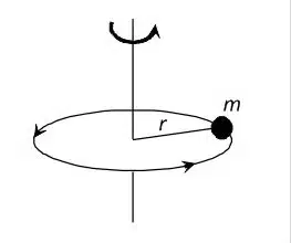
The mass moment of inertia describes the ability of an object to resist angular acceleration, which depends on how the object’s mass is distributed concerning the axis of rotation (i.e., the object’s shape). The mass moment of inertia is usually denoted by the symbol “I.” However, in the technical field, the symbol “J” is commonly used, such as in the inertia specifications of motors and gearboxes. The unit is mass times distance squared: kg m² or lbm-ft² (note that slug-ft² is also sometimes used).
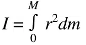
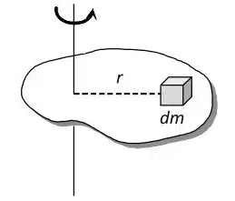
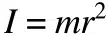
In many applications, an object consists of a center of mass. The mass moment of inertia is simply the mass of that object multiplied by the radius (distance from the axis of rotation) squared.
Mass moment of inertia is important for motor sizing. The inertia ratio (ratio of load inertia to motor inertia) is important in determining whether the motor can effectively control load acceleration and deceleration.
Planar and polar moments of inertia
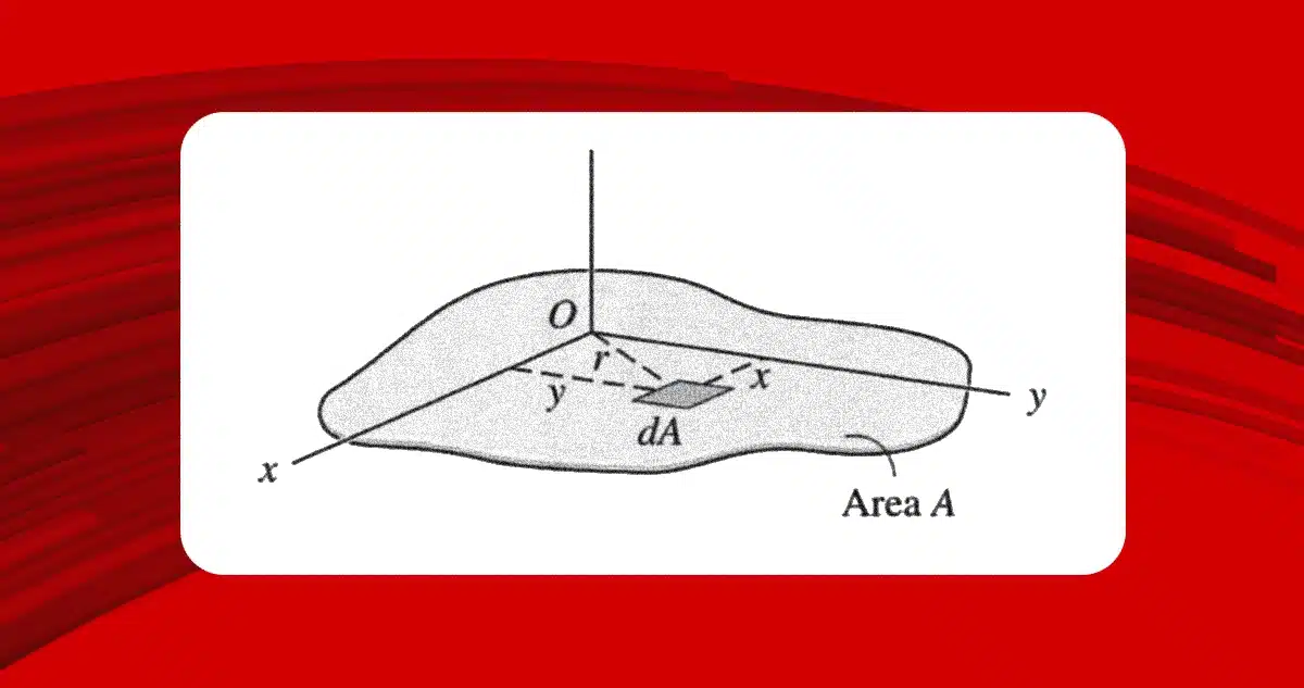
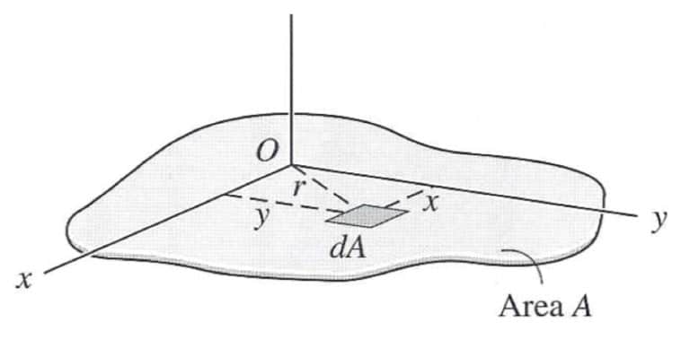
Planar and polar moments of inertia fall under the so-called “second moment of inertia.” The planar moment of inertia describes how an area is distributed with respect to a reference axis (usually the barycentric or central axis). This element is important because it identifies the area’s resistance to bending.
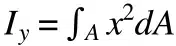
The planar moment of inertia equation uses the second integral of the distance with respect to the reference plane and multiplies it by the differential element of the area. The result is expressed in units of length to the fourth power: m⁴ or in⁴.
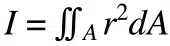
The polar moment of inertia is analogous to the planar moment of inertia but applies to cylindrical objects and describes their resistance to torsion (generated by an applied torque).
The equation for the polar moment of inertia is essentially the same as for the planar moment of inertia. Still, for the polar moment of inertia, the distance is measured with respect to an axis parallel to the area cross-section. The polar moment of inertia is sometimes denoted by the letter J instead of the symbol I, but the units are the same as those given for the planar moment of inertia: m4 or in⁴.
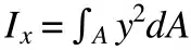
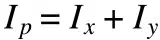
The polar moment of inertia (denoted here as Iᵖ) can also be calculated by summing the planar x and y moments of inertia (Iˣ and Iʸ).
Planar and polar moments of inertia are used to calculate bending, either linear displacement due to an applied force or angular displacement resulting from an applied moment.