At first glance, capacitive or inductive encoders may seem very similar, and the aspects that differentiate them may appear confusing. Both use a noncontact technique for […]
At first glance, capacitive or inductive encoders may seem very similar, and the aspects that differentiate them may appear confusing. Both use a noncontact technique for position measurement and can be constructed using printed circuit boards. However, the physical principles on which they are based are quite different.
This article explains these differences by comparing the positives and negatives that both solutions present.
Capacitive Sensors – Principle of Operation
The discovery of the possibility of storing large amounts of electrical energy can be attributed to scientist Ewald George von Kleist, inventor of the first capacitor. This component consists of two conductive plates (or faces) separated by a dielectric material, typically air, plastic, or ceramic. A simple mathematical model of the capacitor is shown in Figure 1.
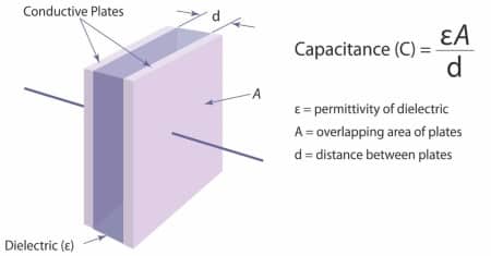
La permittività elettrica Ԑ, ovvero la quantità di energia elettrica trattenuta da un materiale non conduttore sottoposto ad un campo elettrico, è costituita da due parti Ԑr e Ԑ0 dove Ԑr è la permittività statica relativa (anche chiamata costante dielettrica) del materiale tra le due piastre, Ԑ0 la permittività statica nel vuoto. (Ԑ0 = 8.854E-22 F/m).
The capacitive principle is used in devices such as telephones, tablets, and cell phones that employ touch screen technology, meaning they detect the presence or absence of a finger due to the change in the dielectric constant Ԑr that goes into changing capacitance.
A second application is the capacitive displacement sensor, i.e., a capacitive linear scale or rotary capacitive encoder; these sensors work on the change in capacitance between capacitor faces. As shown in Figure 1, capacitance varies in proportion to the distance between the faces (d) and the area of overlap (A). The displacement can be measured axially by varying d or in the planar direction by varying the overlap area A. The capacitor faces can be constructed using printed circuit boards, which provides a significant cost-effective advantage. To store any significant amount of charge, the size d must be small relative to the area of the plates. Usually, d is 1 mm. Linear or rotary capacitive sensors are constructed so that displacement causes a change in A or d. In other words, one face is on the moving element of the sensor, while the other is on the fixed element. As the 2 elements move apart, the capacitance surface C of the capacitor changes.
Unfortunately, permittivity is also affected by factors other than displacement. If the dielectric material is surrounded by air, its permittivity varies with both temperature and the presence of moisture; in fact, water has a different dielectric constant than air; as the permittivity changes, the capacitance changes accordingly. Unless the dielectric material is sealed, capacitive sensors are not suitable for working in environments with high-temperature changes or the likelihood of condensation and/or changes in humidity.
The inherent need to have a very small distance between sensor faces relative to the size of the sensor faces means that great mechanical precision is required for installation. This factor implies a considerable increase in the cost of installation; In addition, one must also consider thermal expansion and the influence that any arising from the structure outside the sensor may have, which will affect the distance between and faces of the condenser and distort the measurement.
In addition, the capacitive effect is based on the conservation of electric charge in the capacitor. If the system around the sensor generates electrostatic charges, these can adversely affect the measurement. In extreme cases, the sensor will not work at all, or, even worse, the electrostatic disturbance will generate a credible but erroneous measurement. Grounding the mechanical system on which the sensor is installed can be a solution and is essential for capacitive angle sensors where the rotating shaft generates static charges from rolling bearings, gears, or pulleys.
Inductive sensors – Principle of operation
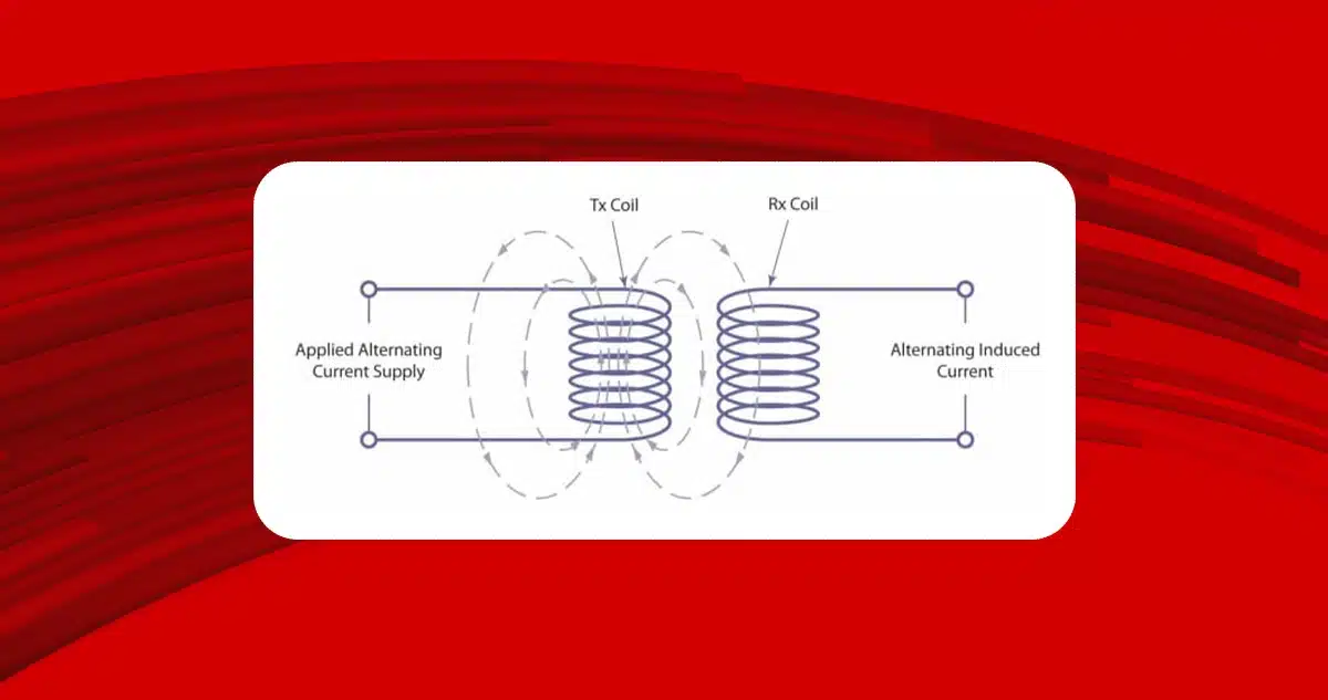
In 1831, Michael Faraday discovered that an alternating current flowing through one conductor could induce a current in the opposite direction in a second conductor side by side with the first. This induction principle is widely used for position and velocity measurement in resolvers, synchros, and LVDTs. The basic theory can be explained by considering 2 windings, one called a transmitter (Tx) to which an alternating current is applied, and the second acting as a receiver (Rx) into which a current is induced:
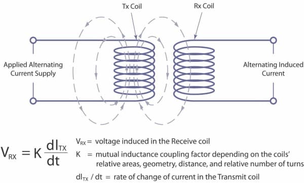
The voltage in the receiving winding is a function of the area of the coils and the geometry of the distance between them. However, as with capacitive sensors, several factors can influence the behavior of the coils for inductive sensors. Temperature is one of them, but it can be eliminated simply by employing more receiving coils and calculating the position from the differential between the received signals (as in a differential transformer). Consequently, if the temperature changes, the effect is nullified since the differential between the received signals is unchanged for a given position.
Unlike systems with capacitive technology, those with inductive technology are less affected by external agents such as water and particles. Because the coils can be spaced widely apart, mechanical precision for installation is less important, and the two elements, the fixed and the movable, have fairly high mounting tolerances. This helps reduce installation costs and allows encapsulation of the components allowing the sensors to withstand external stresses such as vibration and be immune to gaseous substances or dust.
Inductive sensors provide an optimal solution for housing applications in special environments typical of defense, aerospace, and oil industry applications.
One of the major drawbacks of inductive sensors is that they employ ferrite coils for construction, which must be built with special accuracy to obtain an accurate position measurement. Many coils must be employed to obtain a stable electrical signal, making them bulky, heavy, and expensive.
Inductive sensors are considered particularly sensitive to electromagnetic disturbances, but the successful use of resolvers as a suitable element for driving switching and controlling motor speed completely disproves this theory. Both resolvers and LVDTs have been the solution for aerospace or civil applications for many years.
A different approach to inductive sensors
A different approach to inductive sensors is to employ laminar printing technology to make the coils instead of ferrite coils, and this is the solution employed by Zettlex. This entails that the windings can be produced in copper etched or printed on different varieties of polyester or paper films or laminated on ceramic. In this way, very precise windings achieve much higher measurement performance at low cost and low winding weight while maintaining robustness.
Zettlex IncOders are contactless devices between the two main elements, each in the shape of a ring. The large bore makes mounting on through-shafts, slip rings, fiber optics, pipes, and cables easier. IncOrder does not require mechanical mounting with high tolerances, the rotor and stator can easily be screwed to the mechanical parts of the machine. External elements do not affect the measurement, and they are ideal for harsh environments where capacitive devices might be unreliable.
In conclusion
The benefits of the three different sensors are shown in the table below. It can be seen that of the three systems, the one with a non-traditional inductive approach employed by Zettlex lists the most benefits.
| Capacitive | Inductive (Traditional Coils) | Inductive (Printed Coils) | |
| High Resolution | X | X | X |
| High Repeatability | X | X | X |
| High Accuracy | X | X | X |
| Resilience to Dirt, Water or Condensation | X | X | |
| Resilience to electrostatic effects | X | X | |
| Robust EMC OperationLow Thermal Drift | X | X | X |
| Low Thermal Drift | X | ||
| Easy to Install | ? | X | |
| Compact | X | X | |
| Lightweight | X | X | |
| Economical | ? | X |