Stepper motors (or stepper motors) are used in wide-ranging industrial applications. They are inexpensive, simple to operate, and offer high torque at low speeds. However, this type […]
Stepper motors (or stepper motors) are used in wide-ranging industrial applications. They are inexpensive, simple to operate, and offer high torque at low speeds. However, this type of motor has some drawbacks that need to be considered in the design phase; they can lose pitch if the required torque is greater than the available torque, torque drops dramatically as speed increases, they have high resonance frequencies and high power consumption even with only the motor stopped. Galil has three closed-loop driving methods to minimize these drawbacks—correction on the endpoint of positioning, closed-loop microstepping control, and motor driving like a 2-phase brushless.
Source: http://www.vincenzov.net/tutorial/passopasso/stepper.htm
The basics of a stepper motor
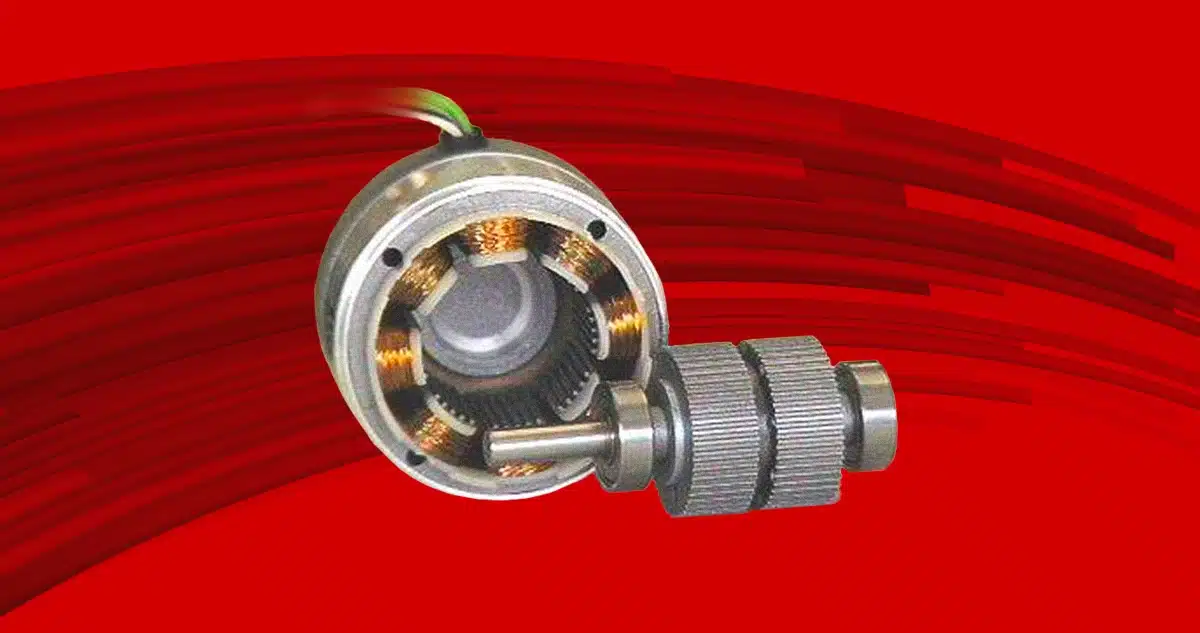
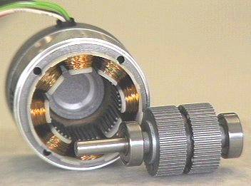
The stator is a set of windings, and the magnetic circuit consists of 4 or, more frequently, 8 “polar expansions” (eight in the one shown photograph). Inside the stator are small teeth that face those of the rotor. The windings, when current flows through them, generate a magnetic field. On the outside come the power wires of the various stator windings; the phases can be wound according to two patterns: in bipolar motors, there are only 2 windings, and 2 pairs of wires come out; in unipolar motors, there are 4 windings wound in pairs in antiparallel on the polar expansions.
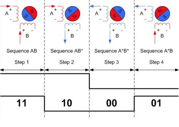
The rotor appears as a pair of massive, mutually identical, side-by-side toothed wheels integral to the shaft consisting of a magnetic core; the two wheels are magnetized, one as NORTH, the other as SOUTH; the “teeth” of the wheels are made of ferromagnetic material. The number of teeth is variable, 50 being the most common. A phase shift between the two wheels is equal to 1/2 the pitch of the teeth: the tooth of one section thus corresponds to the valley of the other. To rotate the shaft, the windings are excited in a specific sequence. Figure 2 shows a simplification of this process in a two-phase motor. Each sequence corresponds to the rotation of one step of the rotor. Typically there are 200 steps per revolution. From the control come out 2 signals, the one called Step, which is a square wave signal to each pulse corresponding to a displacement of one physical step of the motor; the second signal is the Direction set by the high/low state of the signal.
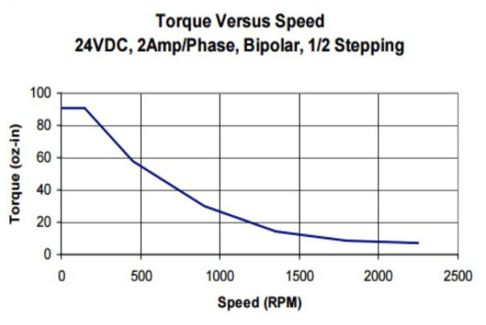
Stepper motors are not immune from defects. First, the motor operates at maximum current under all conditions, leading to wasted energy and increased operating temperature. The second defect is the introduction of vibration caused when the rotor moves from one step to the next. When the frequency of change between successive steps equals the resonant frequency of the motor, the amplitude of vibration increases, leading to loss of position. A common condition for all motors is the drastic decrease in torque as speed increases. It is common to make a mistake in motor selection if this characteristic is not considered at the design stage. A final drawback in stepper motors is the low resolution resulting from the number of steps per revolution. If higher resolution is needed, microstepping technology can be a viable solution.
Microstepping
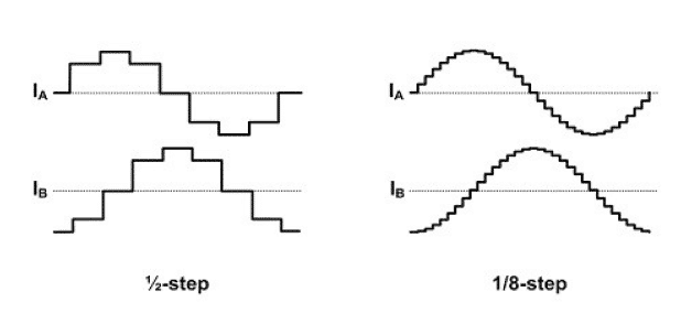
Microstepping stepper motor driving is a method of dividing the whole step into smaller increments. Starting from a microstepping of 2, one can go up to 256 micro-stepping per whole step, which means that a 200-step-stepping motor can have a resolution of up to 51200 micro-stepping per revolution. Figure 4 shows the detail of the current waveform for a single step by increasing the number of micro interpolations.
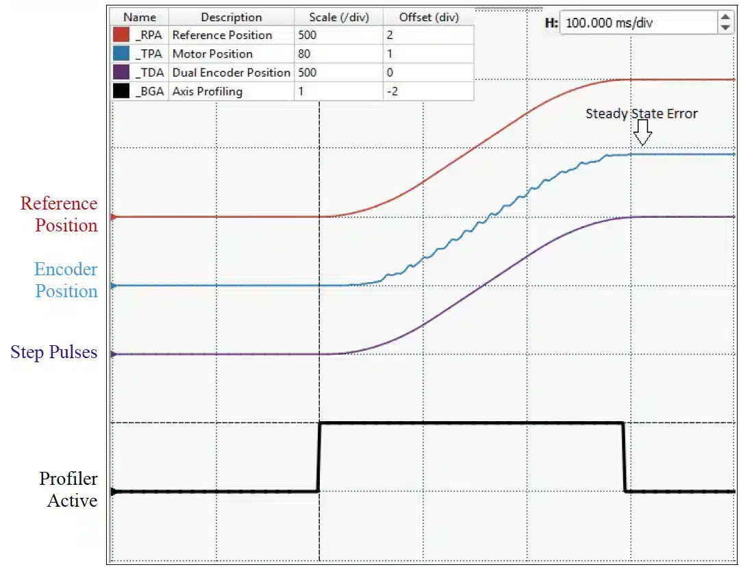
The accuracy achievable with this control technique depends largely on the external force applied. The achievable accuracy is one whole step; a motor stall would result if the position error is greater than half a whole step. A position error will be incurred if friction, gravity, or any other force is large enough to prevent movement between two micro-stepping. Figure 5 shows point-to-point positioning in a system driven by a stepper motor with an encoder. The red line is the theoretical position, the purple line represents the control of the motor, and the blue line is the position measured by the encoder. The black line indicates when the control activates the motion profile. Due to friction, the final position of the motor does not equate to the commanded position, causing a steady-state error.
Correction on the endpoint
By employing an encoder as feedback, it is possible to recognize this situation of position error; the end position can be corrected by imposing an additional command such that the actual position is brought to equal the desired position. Galil calls this mode of driving Stepper Position Maintenance or SPM. The motor is always driven in microstepping, but the accuracy of the endpoint can be checked and adjusted. One compares the commanded position with the actual position before the positioning is finished. Figure 6 shows the same system as in Figure 5 but with SPM piloting. At the end of the movement, the position error is recognized, and a correction command is sent to bring the motor to the desired position.
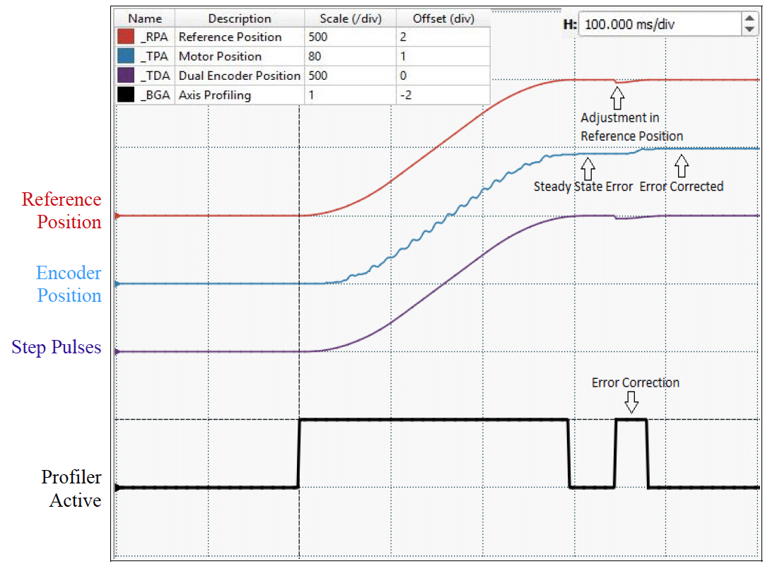
By adding the encoder, the control can recognize and correct the error present in the system. The movement that previously resulted in a stable position error state due to the friction present can now be corrected.
Closed loop microstepping pilot
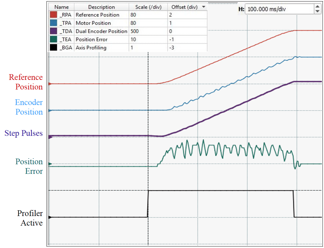
Control via Stepper Position Maintenance mode is ideal for systems requiring only positioning accuracy on the endpoint. Galil suggests using Closed Loop Microstepping or CLS when continuous position error correction is needed. Figure 7 shows positioning in CLS mode. In addition to the commanded position and the actual encoder position, a position error signal is generated internally to the control, green line, and employed to check the commanded position continuously. It is important to note that with CLS mode, the encoder monitors the position, but the control generates the motor command.
The error signal is analyzed by Galil’s internal filter, which compensates for any position error by modulating the control steps to the drive. Closed Loop Microstepping is a real closed loop system and is an ‘excellent solution to control a stepper motor traditionally. A closed position loop involves the risk of having instabilities if the internal filter gains are not properly calibrated. However, the fact remains that this is an energy-inefficient system and has a low bandwidth compared to a classic servo motor system. It should be considered that the bandwidth can be further lowered if third-party drivers with nonlinear characteristics are employed.
Stepper motor drive as a two-phase brushless motor
The stepper motor can be controlled as a two-phase brushless servo motor to achieve maximum performance. The current to the motor is controlled according to the position error exactly as with a servo motor. The control system employing Galil is called 2 Phase Brushless mode or 2PB. Figure 8 shows the detail of a stepper motor controlled in this way. Instead of steps, an analog command in torque mode (brown line) is generated by the control and sent to one of the drives that can be integrated into the control.
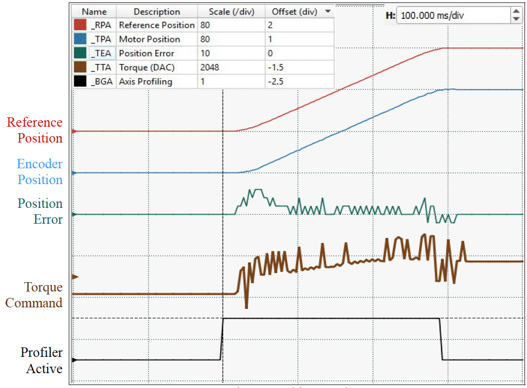
Commanding a stepper motor increases the bandwidth by reducing the positioning time. The motor becomes analogous to a servo motor with a gearbox. Due to the behavior as a servo, the full range of the Galil filter can be employed, including notch, pole, and feedforward filtering. For maximum performance, the drive must be more sophisticated to instantly generate the current required for driving. Energy-wise, greater efficiency is achieved, and the motor will generate less heat.